Assemble the Gear Box
Assemble the Tamiya Robo Craft Series Mechanical Giraffe by following the instructions No. 3, 4, 5, 7.
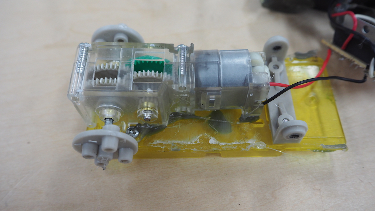
Insert the Motor
Once the gear is assembled, turn it to check that it moves smoothly and insert the motor. Press each of the motor's wires on the ends of a AA battery to check if the gear moves. (At this point, the battery’s polarity does not matter.)
Assembling the Electronics Section
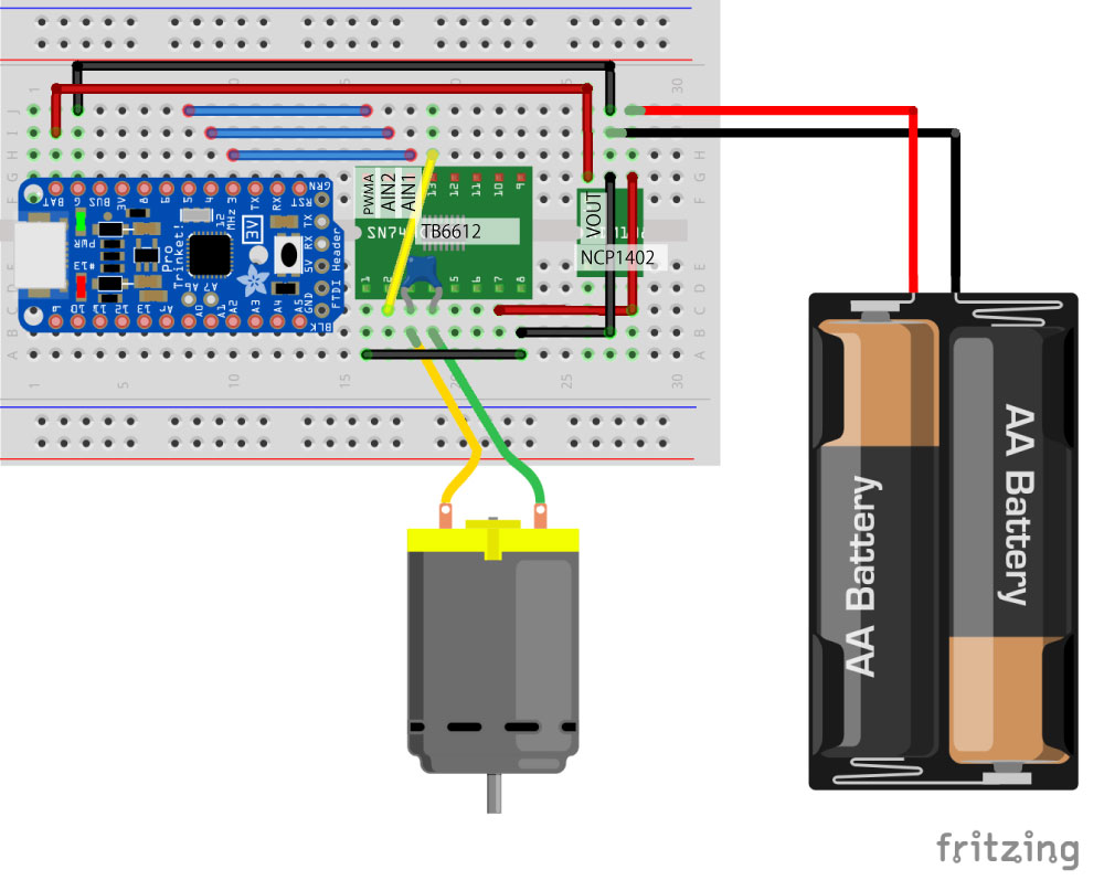
Wire the electronics section that controls the robot’s movements.
(If there are any alternative components, please leave a comment and let us know!)
(If there are any alternative components, please leave a comment and let us know!)
Solder the Components
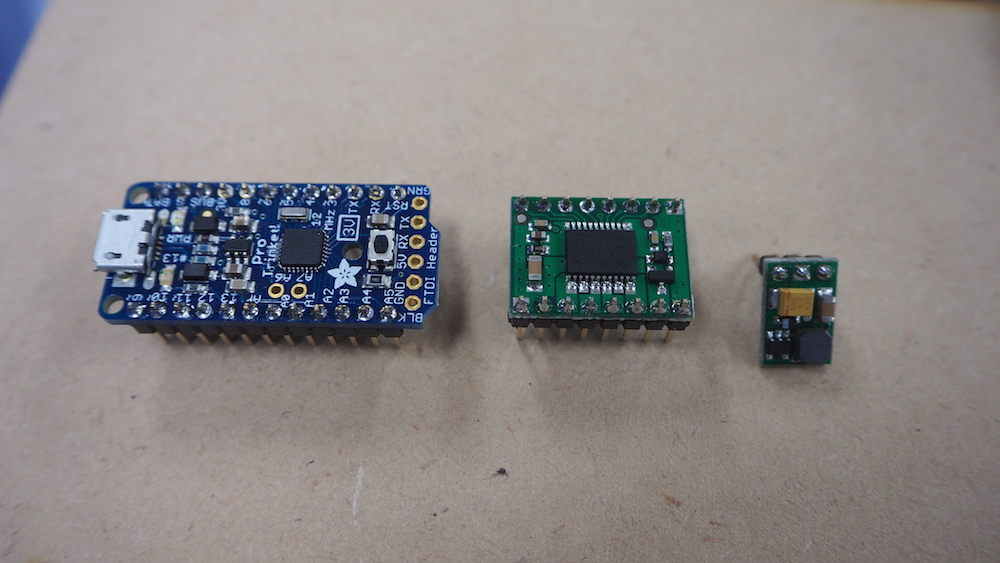
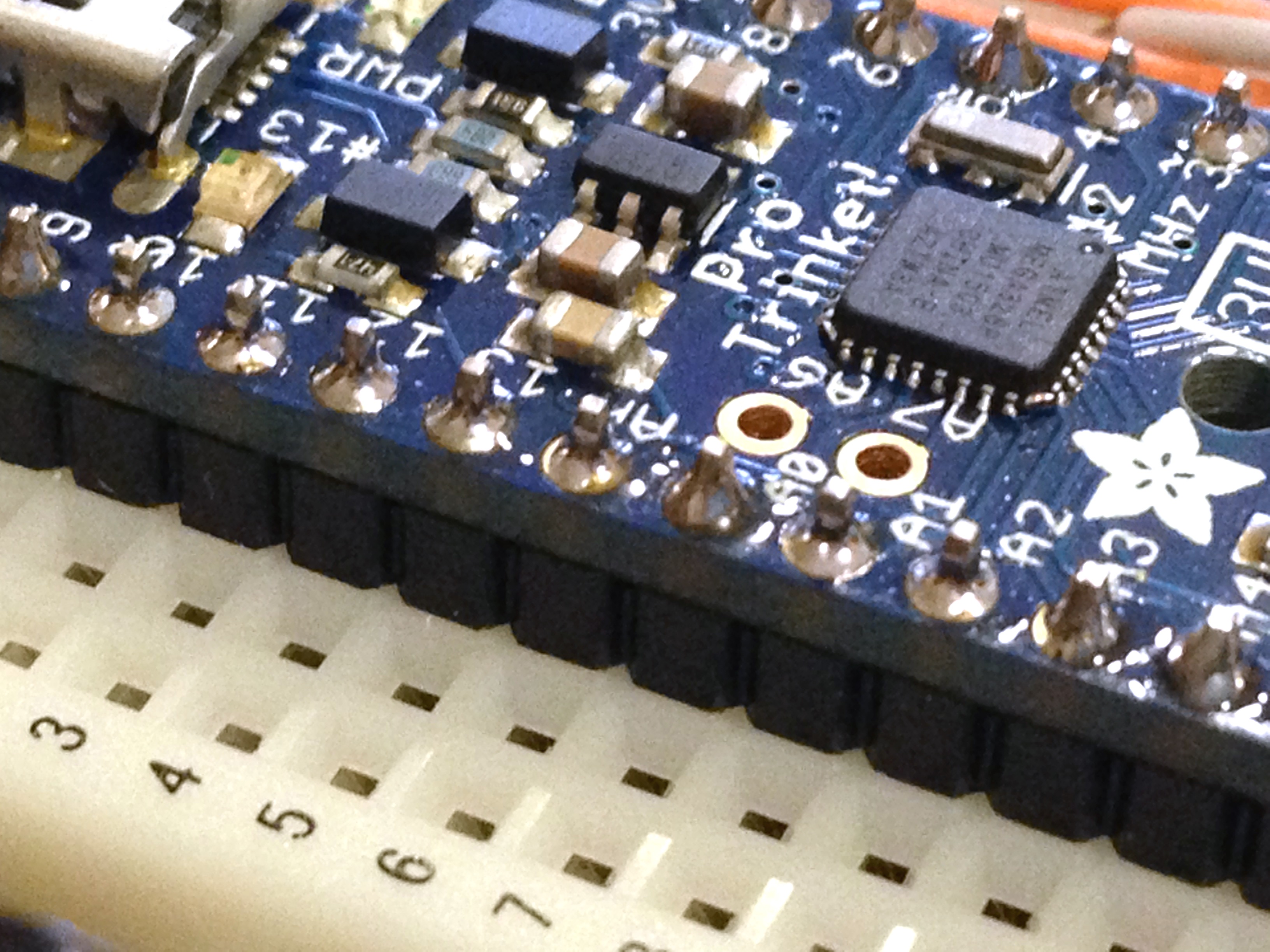
Solder pins headers to the Trinket, motor driver and regulator boards.
For the Trinket, you do not need to solder A6, A7 and the FTDI Header.
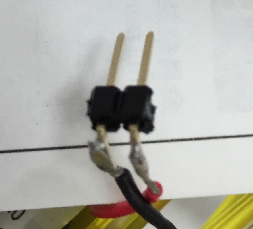
Also solder two pins to the wires of the motor and battery holder, to make it easier to connect to the breadboard.
For the Trinket, you do not need to solder A6, A7 and the FTDI Header.
Also solder two pins to the wires of the motor and battery holder, to make it easier to connect to the breadboard.
Soldering Tips
Inserting the pins to the breadboard and placing the board on top will make it more stable to solder the pins.
※ Too much heat can damage the chip on the board. Let the board cool down every 5 seconds you solder.
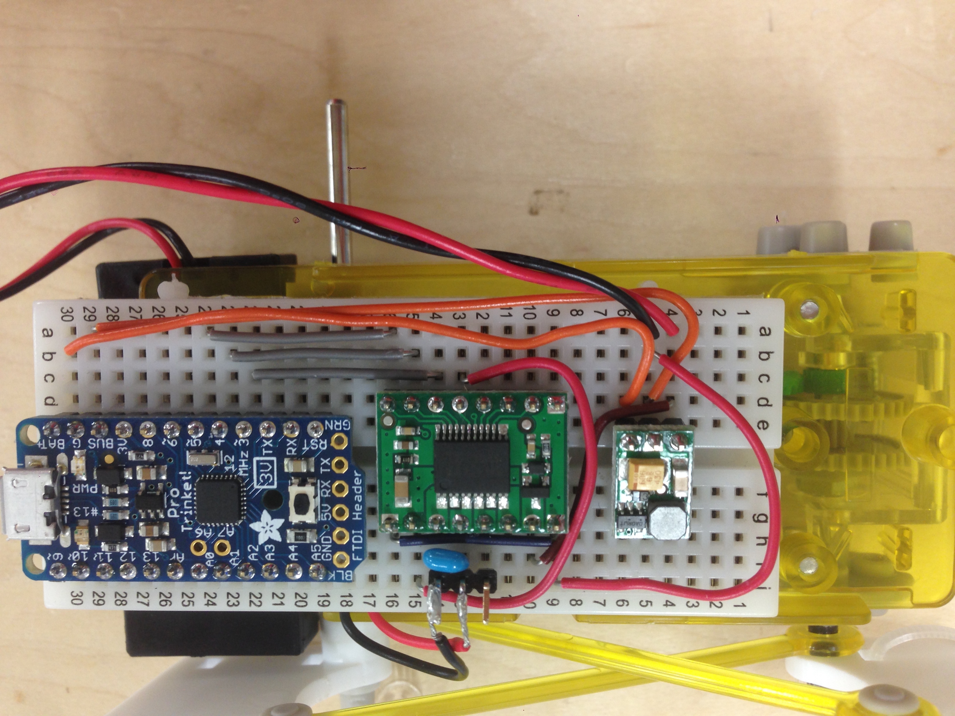
Wire the Components
Break off both ends of the bread board so that it will fit in the case.
Be careful of the direction of the components. Refer to the previous pictures and pin names printed on the bottom of the board
Connect the motor afterwards.
Be careful of the direction of the components. Refer to the previous pictures and pin names printed on the bottom of the board
Connect the motor afterwards.
Upload the Sketch (1)
Upload the following Sketch Program to Trinket.
・Since the standard ArduinoIDE does not recognize Trinket, download Arduino 1.6.x IDE ・Open the IDE
・Since the standard ArduinoIDE does not recognize Trinket, download Arduino 1.6.x IDE ・Open the IDE
・From the menu at the top of the screen, select [Tools] → [Board] and select Pro Trinket 3V/12MHz(USB)
・Do not select the Serial Port
Upload the sketch (2)
・Open this sketch program
・From [Tools] → [Programmer] select USBtinyISP
・Connect the Trinket to the PC with a USB2.0 A-miniB Cable.
・While the red LED is blinking, press the upload button at the top left of the window (the button with a right arrow).
・From [Tools] → [Programmer] select USBtinyISP
・Connect the Trinket to the PC with a USB2.0 A-miniB Cable.
・While the red LED is blinking, press the upload button at the top left of the window (the button with a right arrow).
Memo: If There Are Errors When Uploading
avrdude: Error: Could not find USBtiny device (0x1781/0xc9f)
When this error appears, eject and insert the USB cable and upload the sketch while the red LED is blinking.
Or try using the USB 2.0 Cable.
Or try using the USB 2.0 Cable.
Attach the Battery Holder
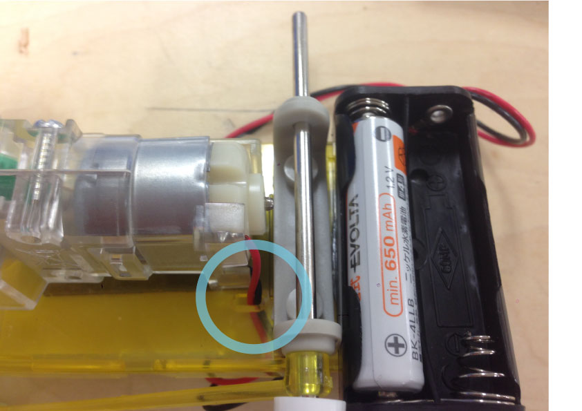
Attach the Battery holder next to the gearbox with both sided tape.
If the motor’s wires are too short, put it through the hole as shown in the picture.
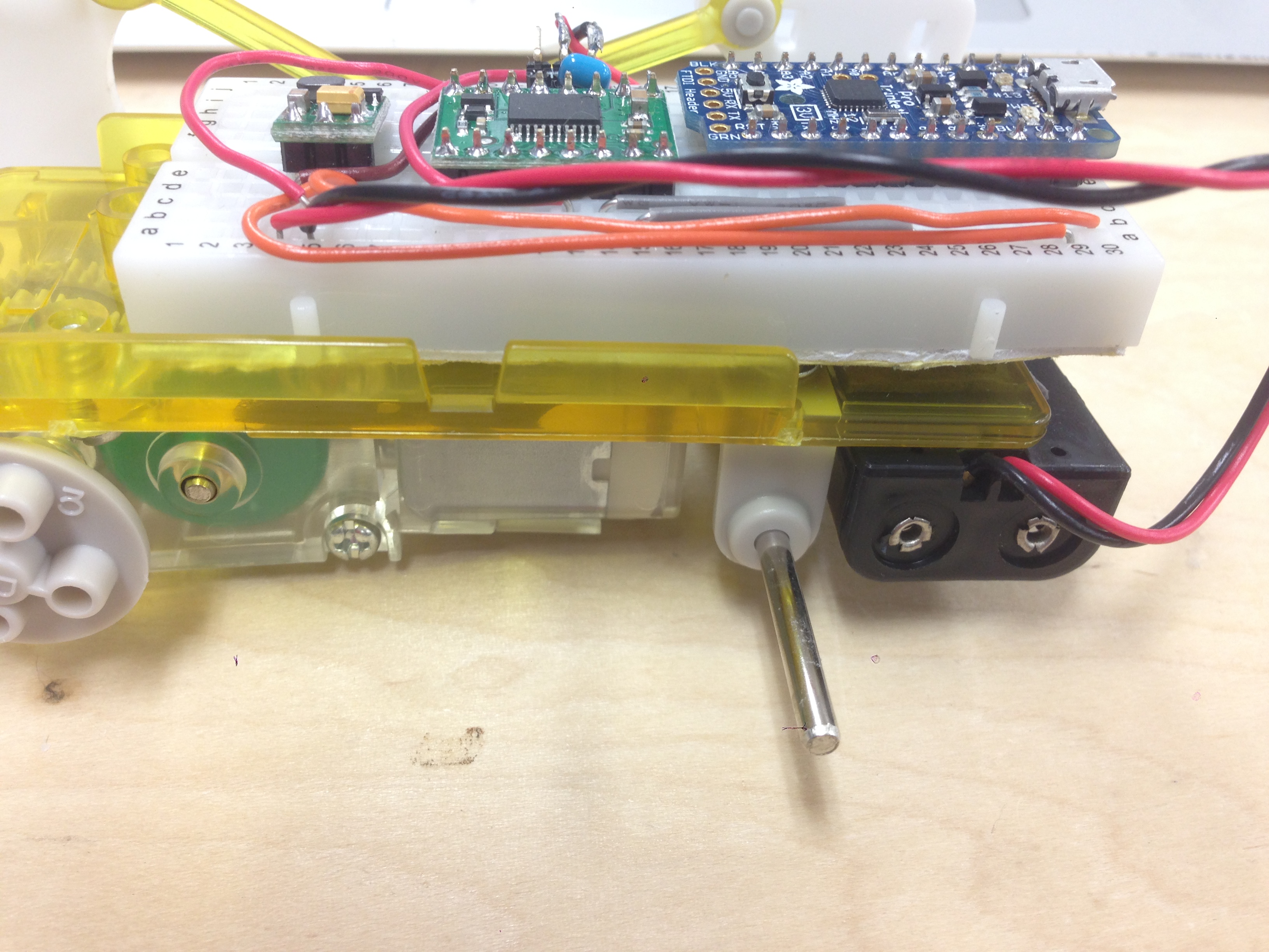
Attach the Breadboard to the Gearbox
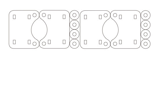
From the yellow plastic part, cut off two of the the smaller cylinders with a nipper.
Attach the breadboard with thick both sided tape. Since the head of the screw gets in the way, using thick tape will make it easier to attach the breadboard.
Attach the breadboard with thick both sided tape. Since the head of the screw gets in the way, using thick tape will make it easier to attach the breadboard.
Make and Assemble the Top Part of the Leg
Attach the Pieces to the Gearbox (1)
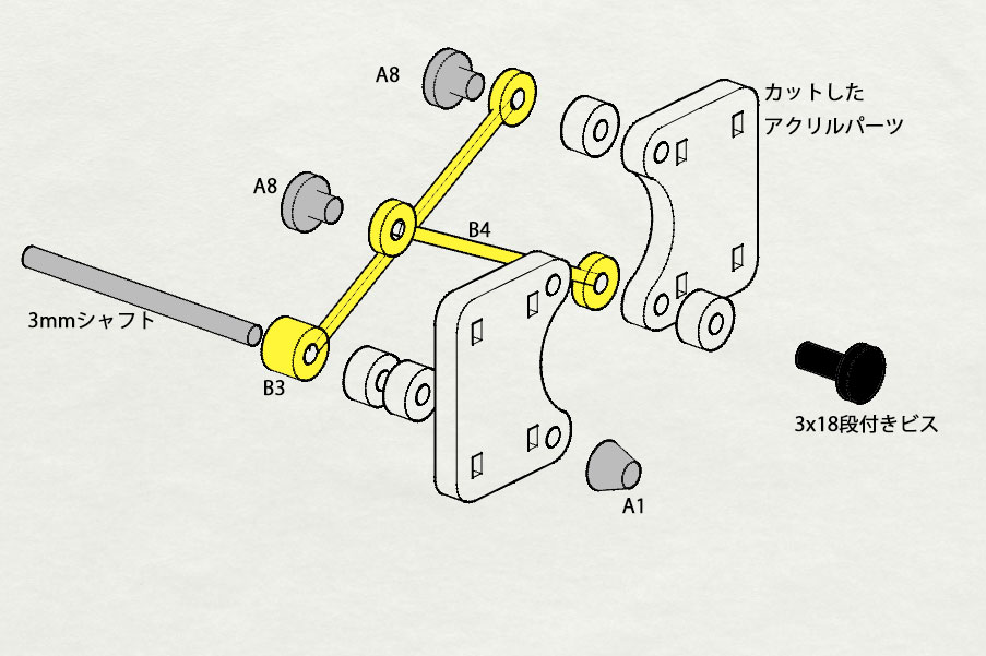
Referring to the image above and the Mechanical Giraffe’s instructions (No. 7, 8, 9), assemble the laser cutter pieces with the Mechanical Giraffe’s pieces.
Be careful of the direction and order of the pieces
Be careful of the direction and order of the pieces
Attach the Pieces to the Gearbox (2)
The grey pieces (A8) may be hard to insert through the hole, so use a plier.
If A8 does not fit, use a M3 screw and nut instead.
If A8 does not fit, use a M3 screw and nut instead.
Check Its Movement
Insert Two AA batteries into the battery holder and check the Fabwalker’s movement. (At this point it won't be able to walk.)
Chargeable lithium ion batteries such as eneloop are stable since they do not have voltage drops. Supply 3V with two batteries.
Chargeable lithium ion batteries such as eneloop are stable since they do not have voltage drops. Supply 3V with two batteries.
Gather Materials for the Robot’s Feet
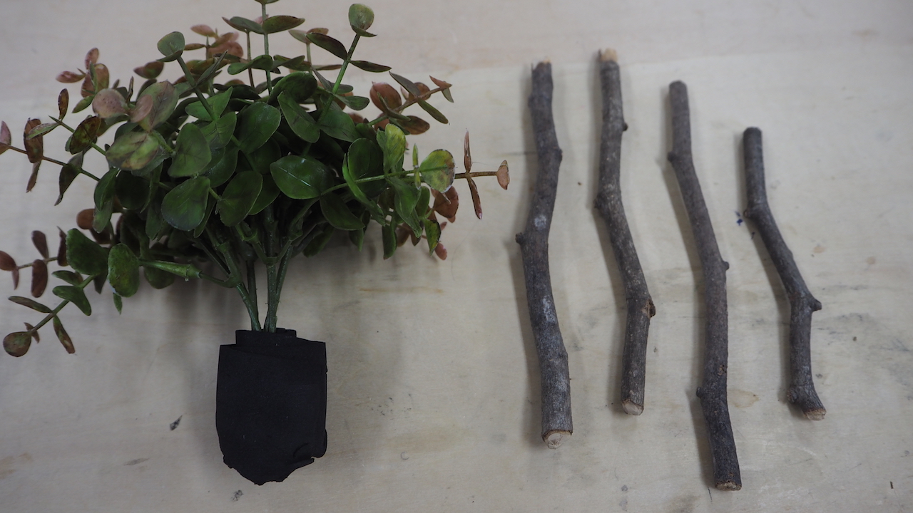
Gather Material for the Robot’s Feet, such as branches of a tree, flowers and grass.
Or you can use household items such as pens and tooth brushes.
Or you can use household items such as pens and tooth brushes.
Attaching the Legs
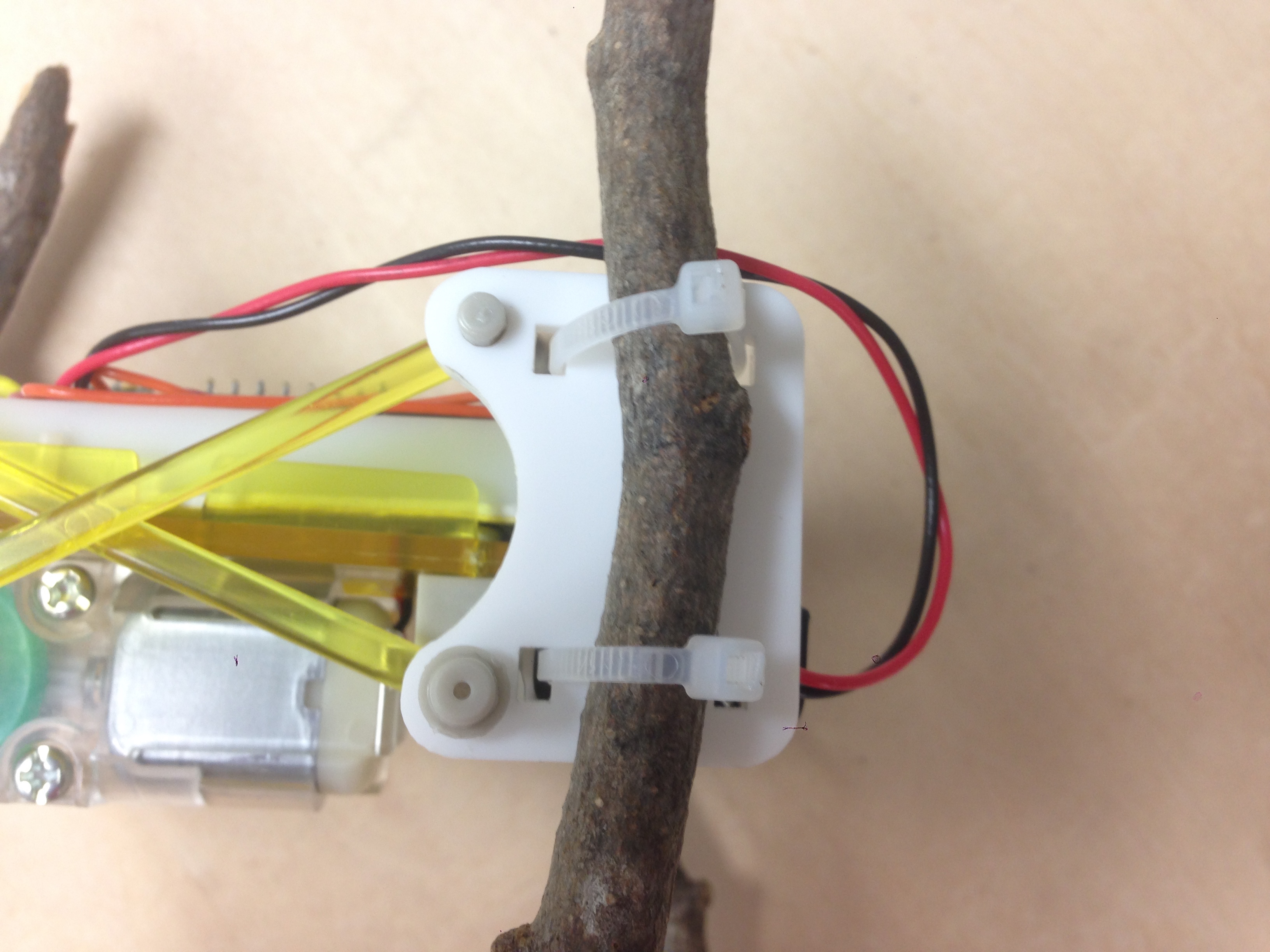
Use Cable Ties or Twist Ties to attach the legs to the Fabwalker’s body.
Something that can be used repeatedly.
(If you know a better way to attach the legs let us know in the comments. We used rubber bands for the previous version.)
(If you know a better way to attach the legs let us know in the comments. We used rubber bands for the previous version.)
The Fabwalker is Complete!
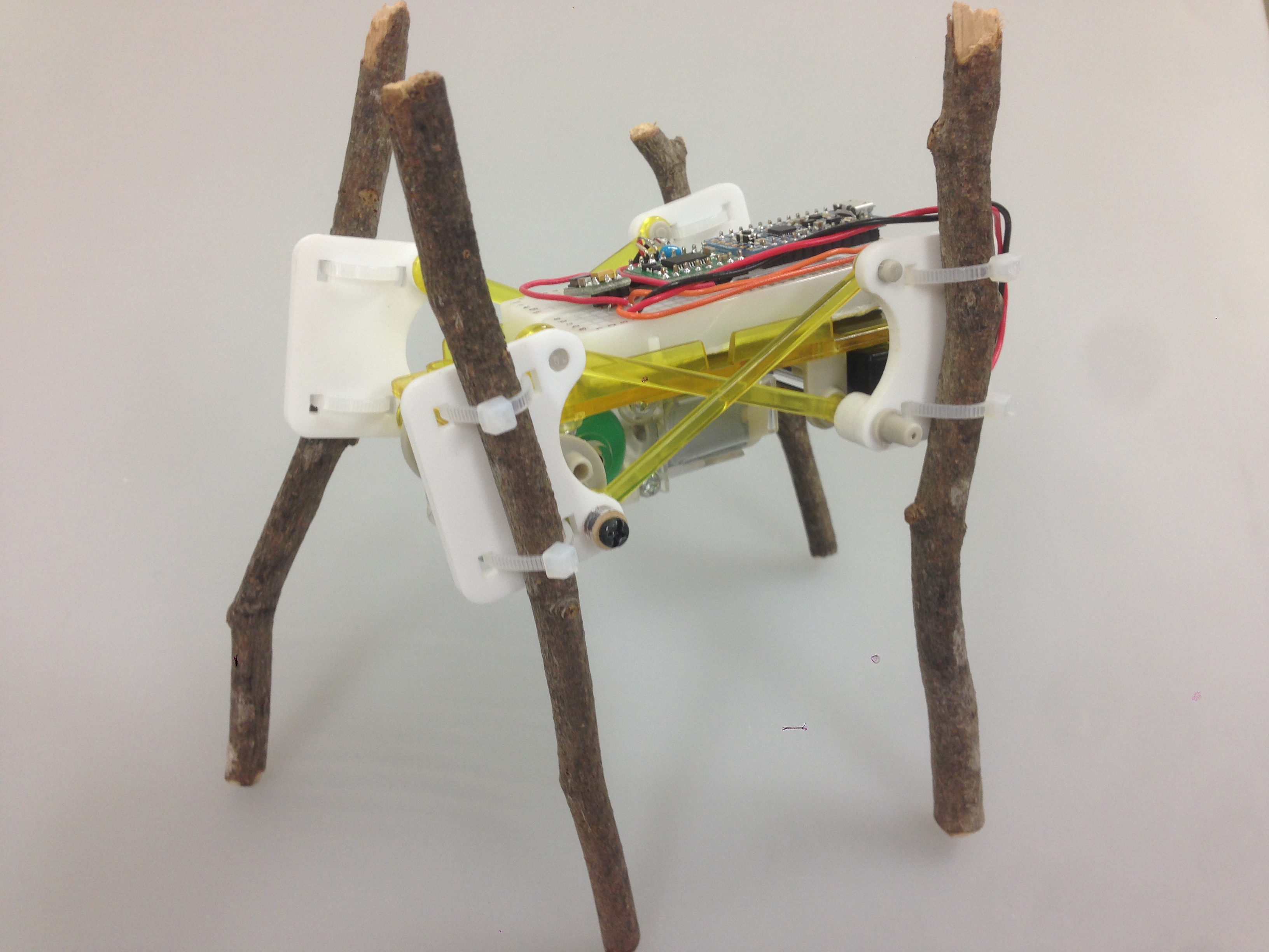
Insert the batteries, and the Fabwalker will come to life!
It will be better to make a case to cover the electronics. For the WalkingTree version we 3D printed a case, put plants in it and made plants walk.
It will be better to make a case to cover the electronics. For the WalkingTree version we 3D printed a case, put plants in it and made plants walk.
歩く様子
足の付け方や長さ、素材によって歩き方が変わってきます。
きちんと前進するベストな歩き方を探してみてください!
(動画はちょっと曲がりながら歩いてます。。)
補足:代替品情報
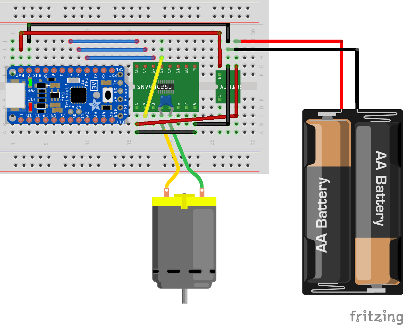
デュアル・モータードライバTB6612FNG(連続最大1.2A)
※代替品ドライバだとピン配列が若干違います。配線図は画像のようになります。
(まだ繋げてないので動かなかったらコメントおねがいします)
秋月のブレッドボード(こちらじゃないと両端の部分が取れない?)