1. Before starting to craft
Processing hole & Frame data
Materials
Prepare
copper-clad laminate (cut substrate), resistor.
*You should calculate
to prepare appropriate LED and resistor.
2. Preparation for cutting
Use different endmills for circuit and exterior frame
Circuit: Endmill ZEC-100 (cutter for words)
Exterior frame: Endmill ZHS-200 (straight endmill)
Prepare a board 4~5 cm thick and attach it to a work table of SRM-20 with double-faced tape. (If you are experienced, you might want to do leveling)
Circuit: Endmill ZEC-100 (cutter for words)
Exterior frame: Endmill ZHS-200 (straight endmill)
Prepare a board 4~5 cm thick and attach it to a work table of SRM-20 with double-faced tape. (If you are experienced, you might want to do leveling)
2-1. Attaching an endmill
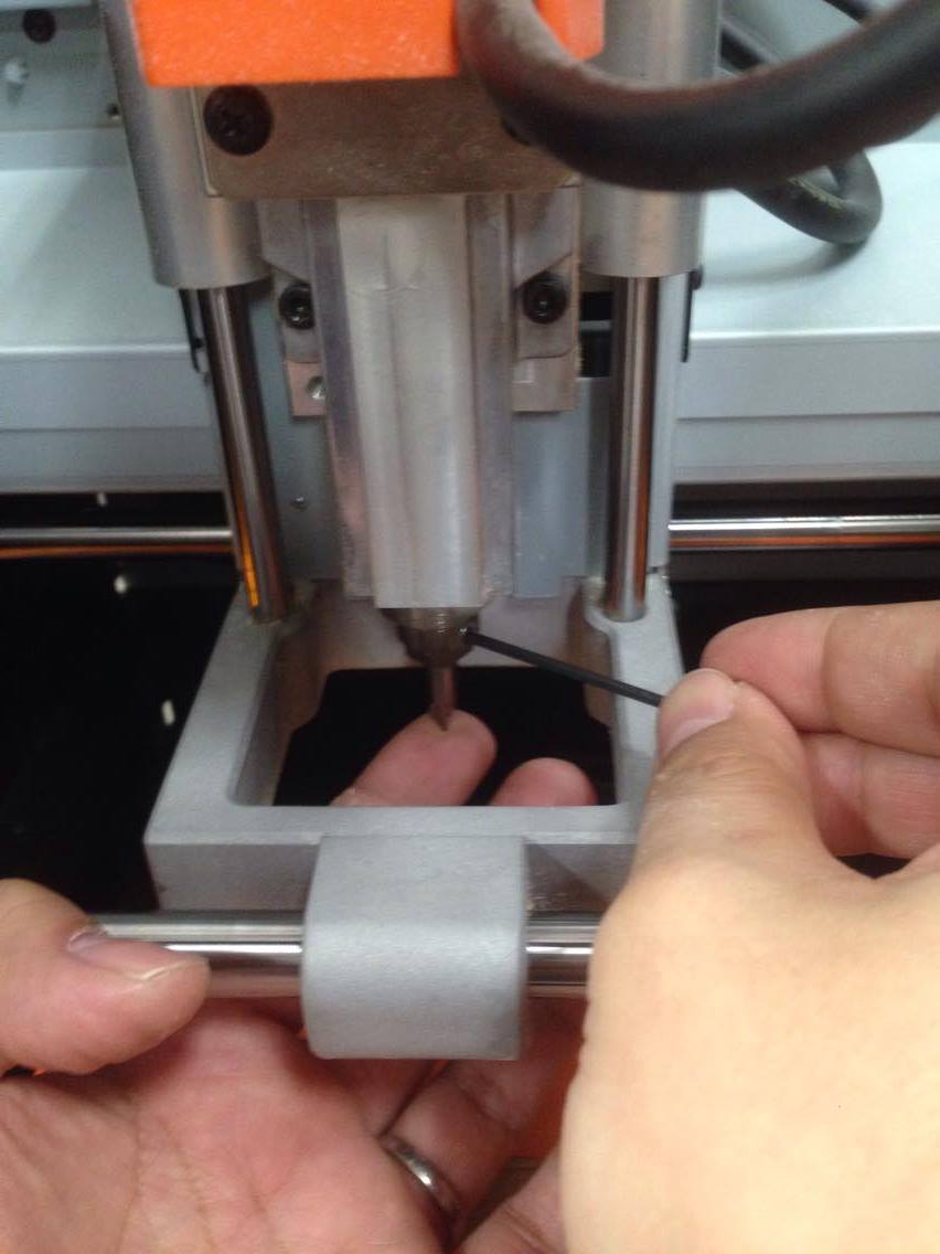
Attach Endmill ZEC-100 (cutter for words).
Support blade edge with your finger to prevent it from falling down.
*Please be careful not to drop the endmill, or its blade edge might get broken.
Support blade edge with your finger to prevent it from falling down.
*Please be careful not to drop the endmill, or its blade edge might get broken.
2.2 Activating VPanel
2.3 Adjustment of the origin of XY
Adjust the origin of XY to the left front side of the substrate.
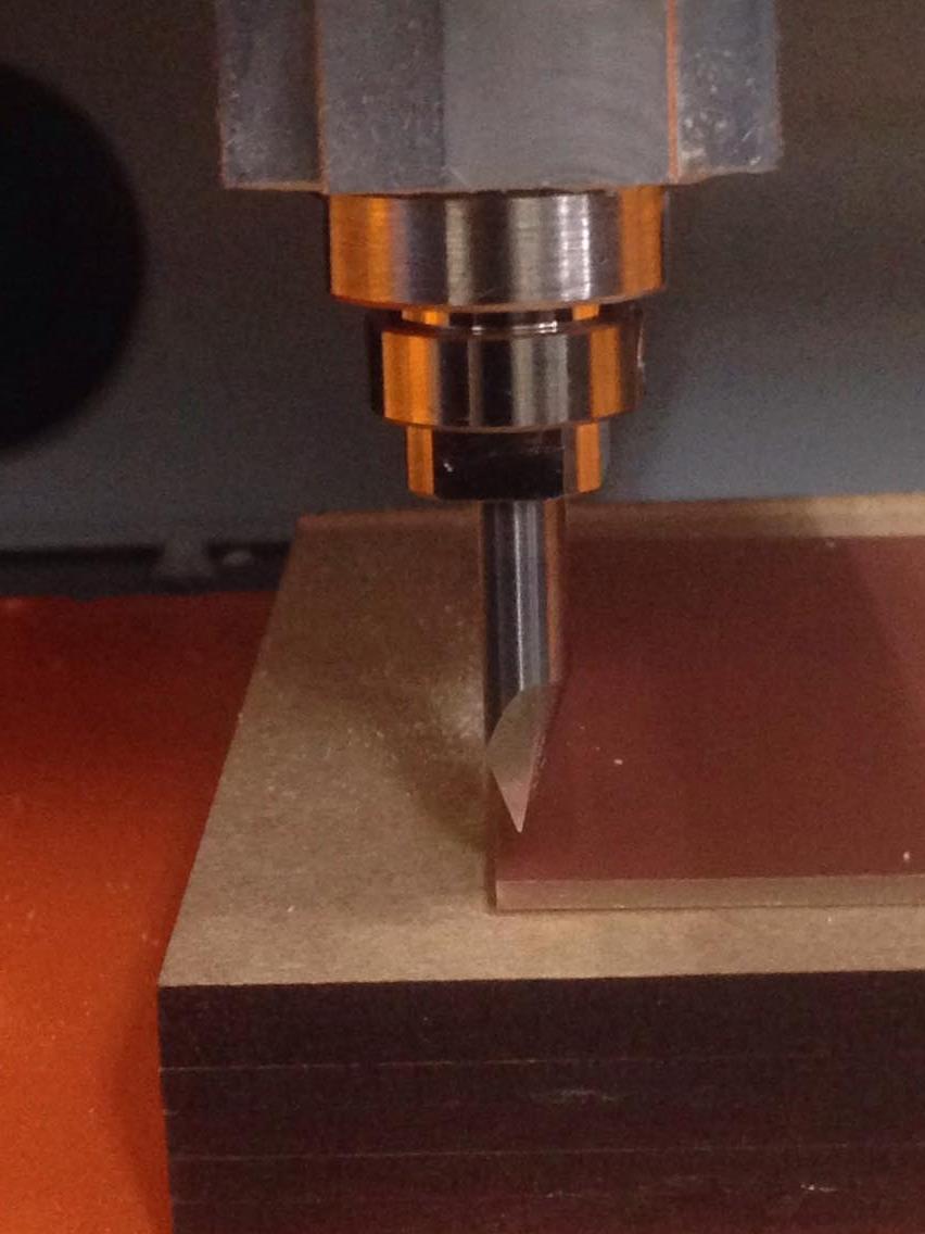
2.4 Adjustment of the origin of Z
Use arrow keys to move endmill close to the substrate. (Be careful that it does not touch the substrate at this point)
Use a wrench to loosen the fixation and pull down the endmill manually so that it barely touches the ground.
Use a wrench to loosen the fixation and pull down the endmill manually so that it barely touches the ground.
※
*If you drop it, blade edge of fine endmill might get broken. Use your finger as in 2-1.
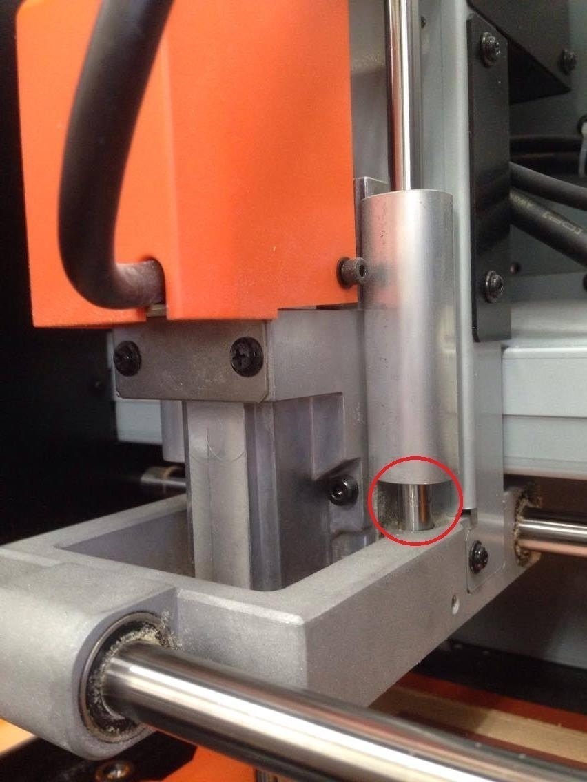
*Make sure that a part indicated by a red sphere has about 1cm space. Otherwise, the endmill does not move down any further.
*Make sure that a part indicated by a red sphere has about 1cm space. Otherwise, the endmill does not move down any further.
2.5 Lifting up the endmill before processing
After adjusting the origin, lift up the endmill by using arrow keys to move it up in Z direction.
Keep VPanel activated, and go to the next step.
Keep VPanel activated, and go to the next step.
Making circuit
After adjustment of the origin, load png files and start cutting.
Activate iModela Creator (software accompanied with SRM-20) and load files as follows.
Activate iModela Creator (software accompanied with SRM-20) and load files as follows.
3-1.Loading the circuit file
Select [file]→[open] in iModela Creator, open circuit.imd, and select whole circuit.
3-2.Configuration of cutting
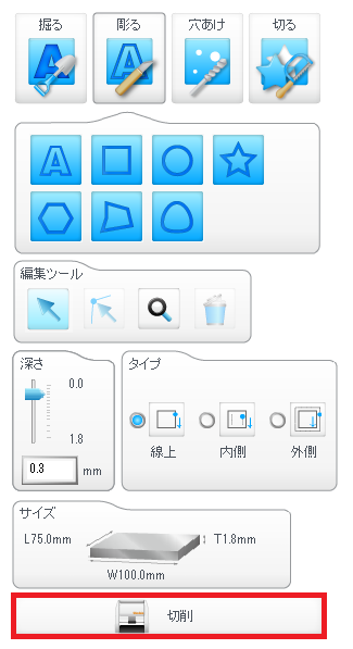
Press “cutting.”
3.3 Configuration of a cutter, materials, and a printer
1. Check [square] in [configuration of a cutter] section, and enter 0.4 as thickness of a cutter.
2. Select foam material in [material] section.
3. Select Roland SRM-20 in [printer] section.
4. Press [condition of cutting] and go to the next step.
2. Select foam material in [material] section.
3. Select Roland SRM-20 in [printer] section.
4. Press [condition of cutting] and go to the next step.
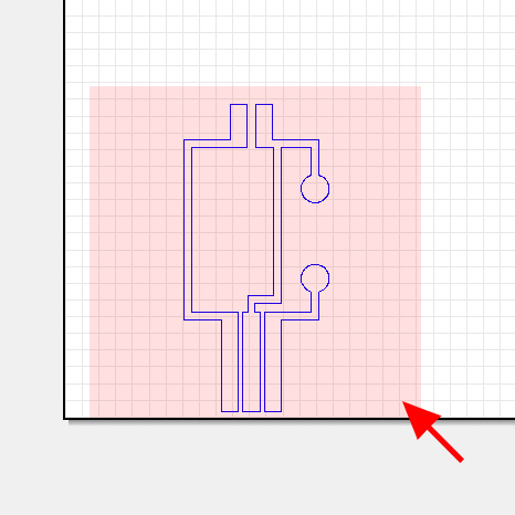
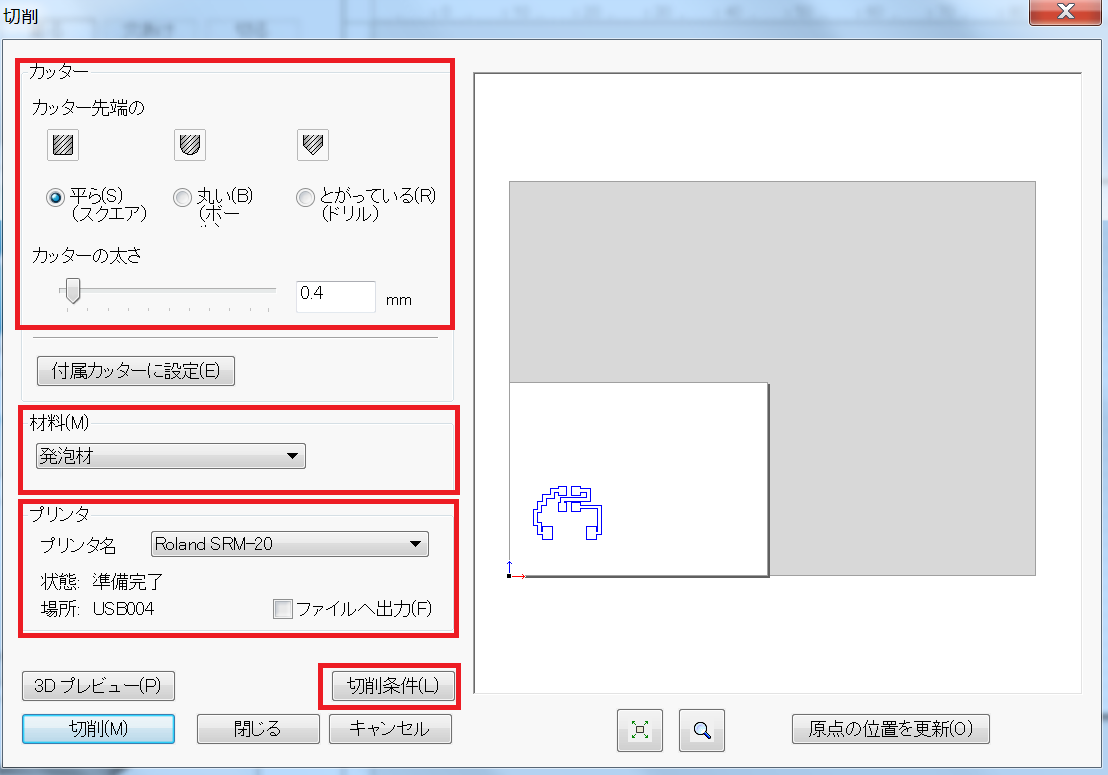
3.4 Configuration of condition of cutting
Set values as indicated in the right figure.
3.5 Start cutting
Start cutting by pressing [cutting]. When a message about VPanel will come up, press OK. We have already finished configuration of VPanel.
4. Replacement of an endmill and adjustment of the origin of
After cutting of circuit is finished, replace the endmill to Endmill ZHS-200 (straight endmill).
Refer to Step 2 about how to replace an endmill.
Refer to Step 2 about how to replace an endmill.
4-1.Adjustment of the origin of Z
You must adjust the origin of Z again after replacement of the endmill.
Refer to Step 2 about how to do it.
*Do not adjust the origin of XY. (You do not need to do that because materials did not move)
Refer to Step 2 about how to do it.
*Do not adjust the origin of XY. (You do not need to do that because materials did not move)
Processing of holes and cutout of exterior frame
The next step is processing of holes and cutout of exterior frame
5-1.Loading the file of holes
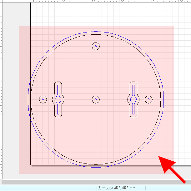
In iModela Creator select [file]→[open] and open hole.imd you have downloaded.
Select whole lines.
Select whole lines.
5.2 Configuration of a cutter, materials, and a printer
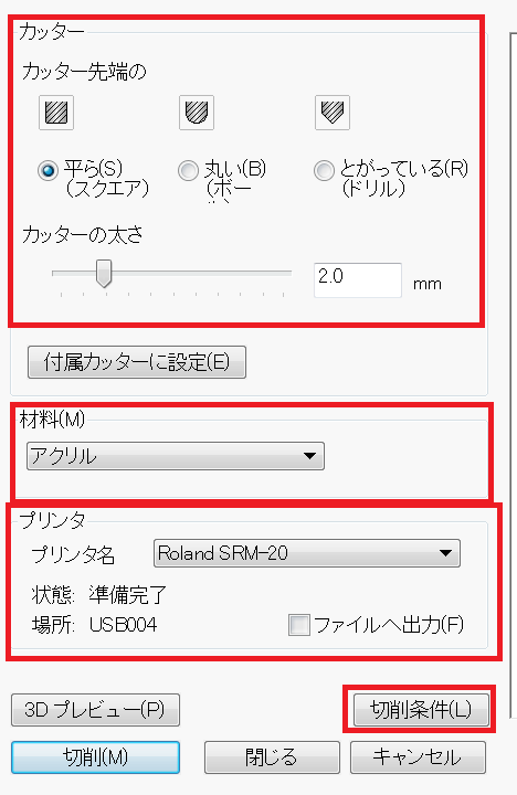
As in 3.3, press [cutting], and setting screen of cutting will appear.
1. In [configuration of a cutter] section, check [square] and enter 2.0 as thickness of a cutter.
2. Select acrylic in [material] section.
3. Select Roland SRM-20 as a printer.
4. Press [condition of cutting] and go to the next step.
1. In [configuration of a cutter] section, check [square] and enter 2.0 as thickness of a cutter.
2. Select acrylic in [material] section.
3. Select Roland SRM-20 as a printer.
4. Press [condition of cutting] and go to the next step.
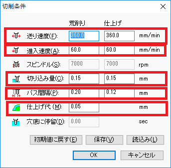
5.3 Setting of condition of cutting
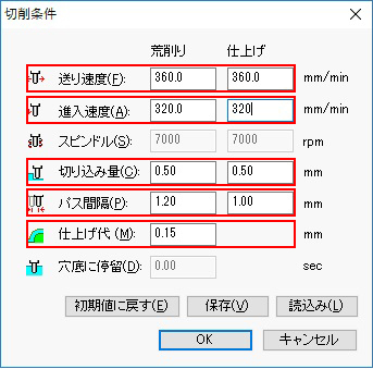
Set the condition of cutting as indicated in the figure.
5-4.Start cutting

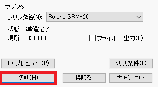
As in 3.5, start cutting by pressing [cutting].
Removal
Referring to “How to make substrate with SRM-20,” remove the substrate with a scraper and remover.
Soldering
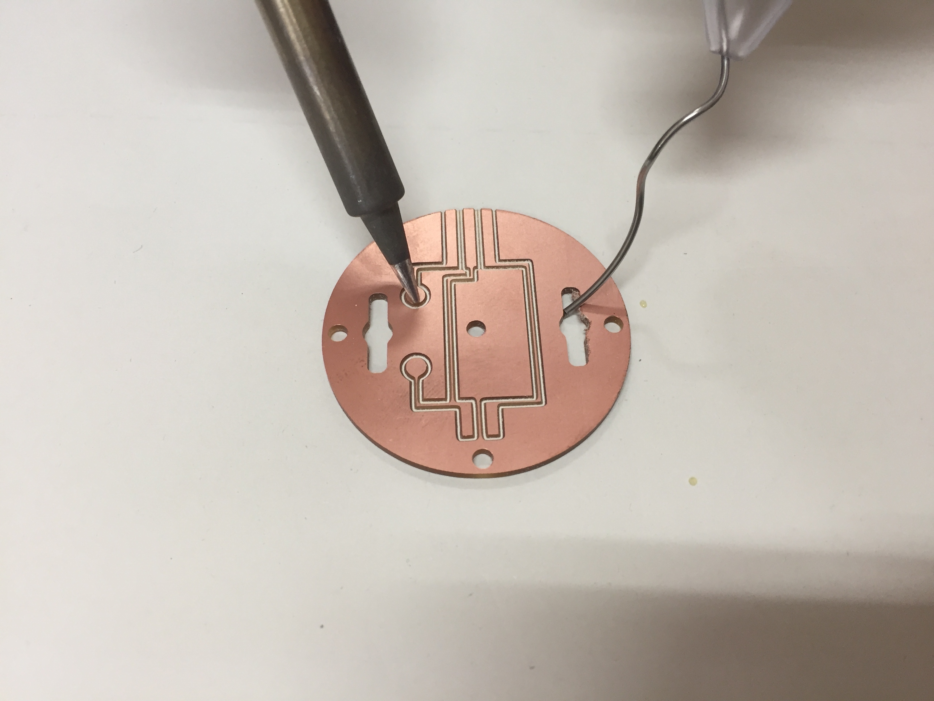
Solder resistor, LED, and a battery box.
brightness sensor
What you need for the brightness sensor
· CdS cell(sensor to sense light / dark)
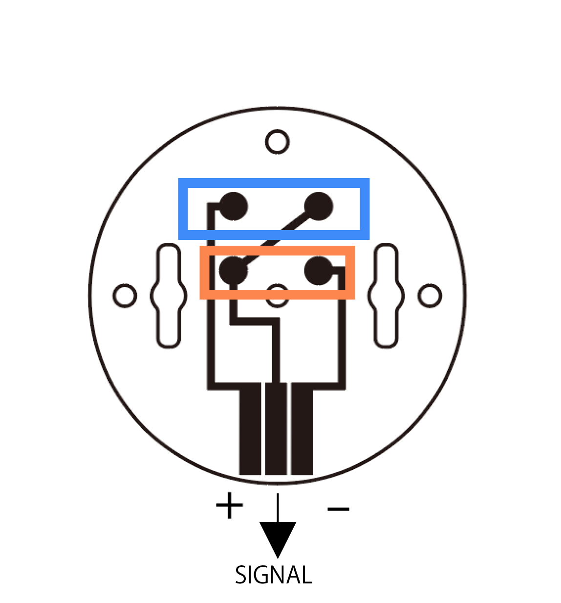
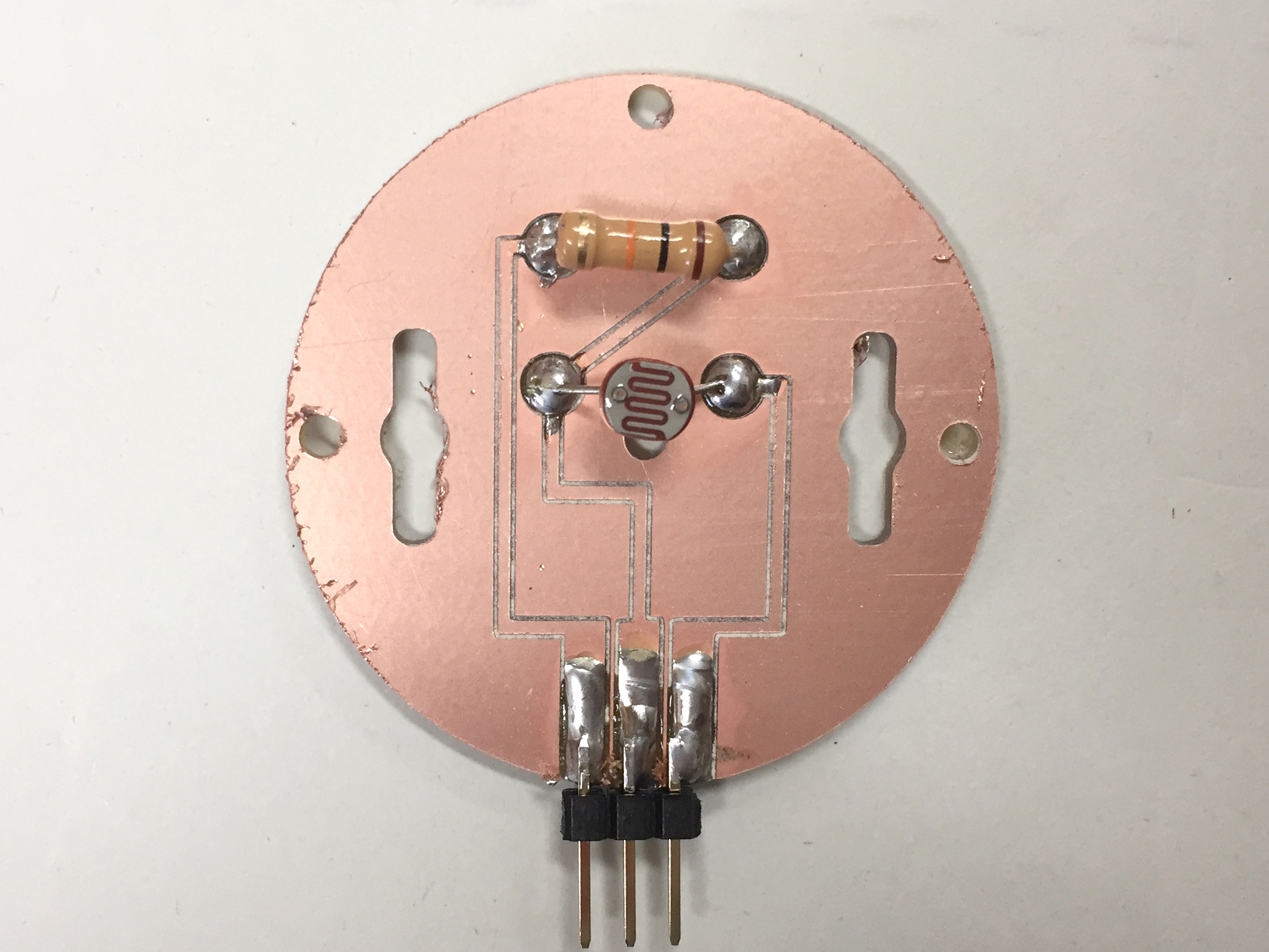
Please solder the resistance to the blue part, the CDS cell to the orange part, the pin header to the three vertical black parts.
pressure sensor

What you need for a pressure sensor
· pressure sensor(sensor to sense pressure)
·resistance(10KΩ)
· pin header(3pin)
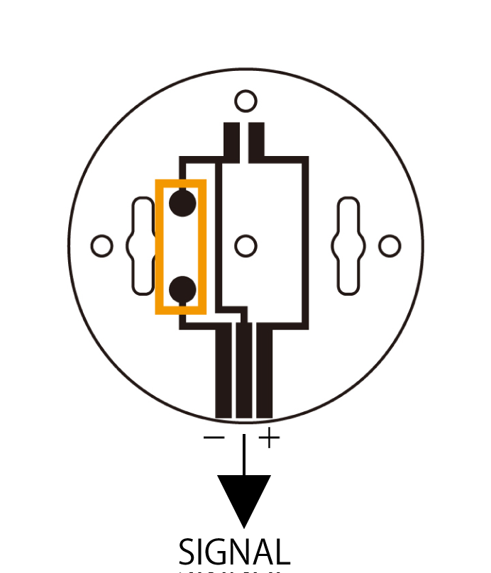
Please solder the pressure sensor to the orange, the pressure sensor to the black on the top two, the pin header to the three vertical black.
short range sensors

What we need for short range sensors
· pin header
Please solder the resistance to the blue part and the orange part, the photo reflector to the red part, the pin header to the three vertical black parts.
LED
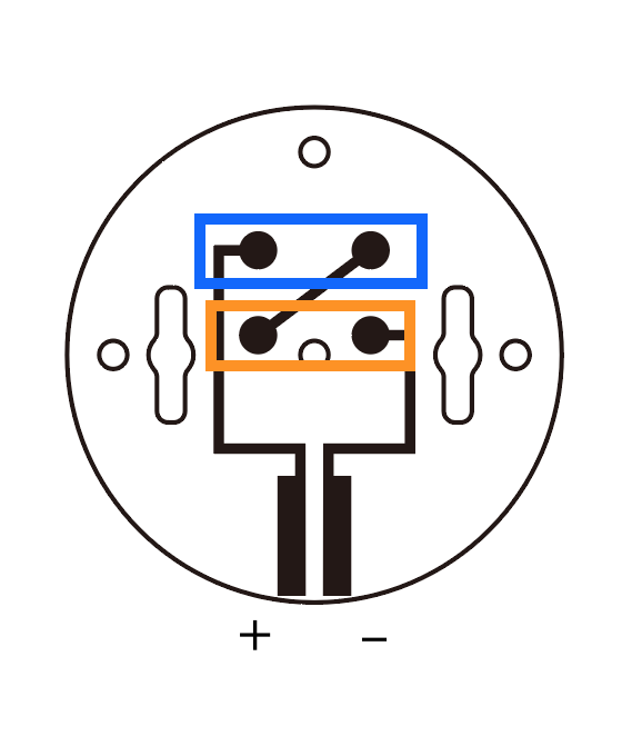
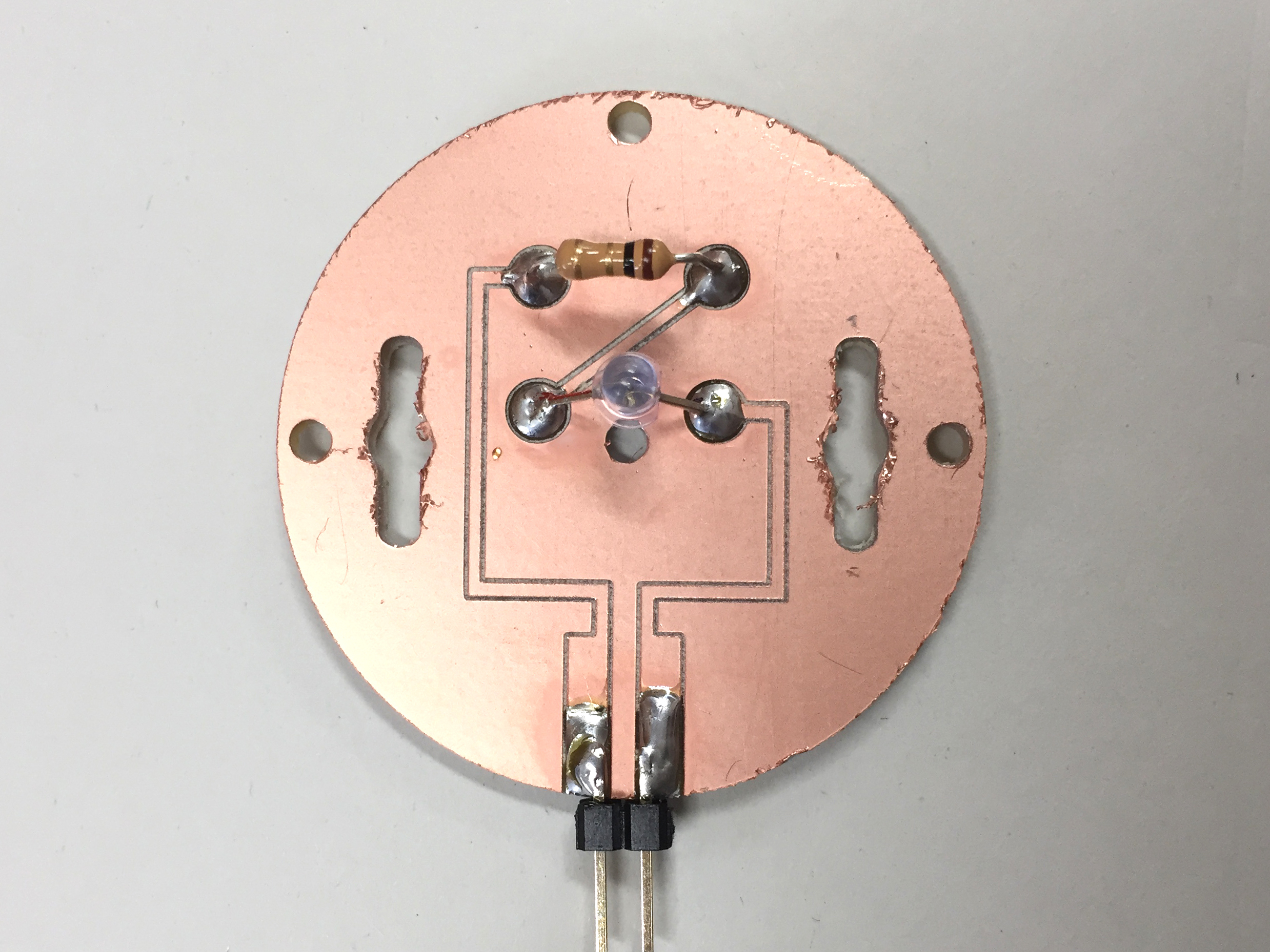
What we need for LED
· White LED (You can change the color by turning on the cap)
Please solder the resistance to the blue part, the LED to the orange and the pin header to the three vertical black parts.
motor
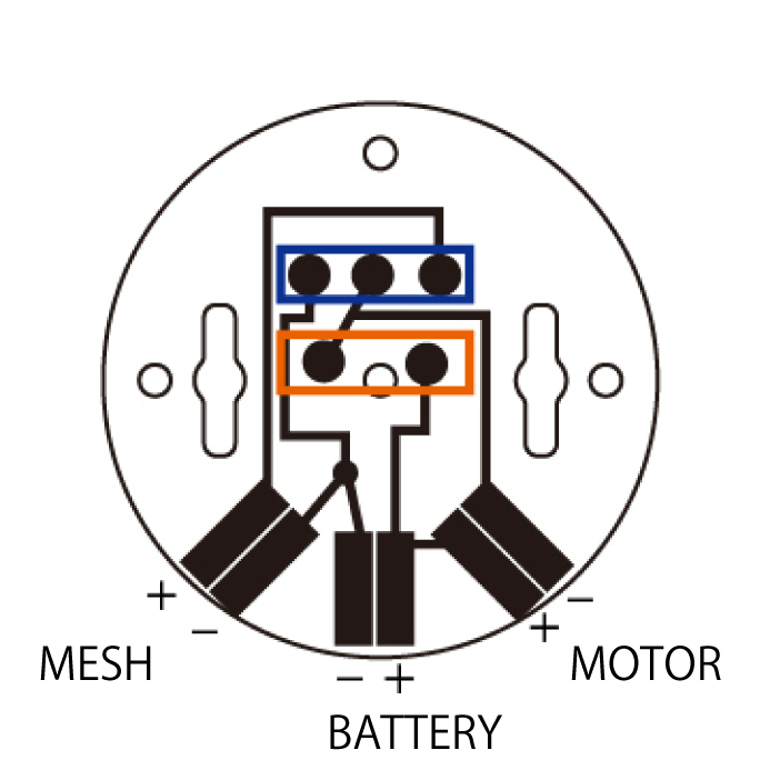
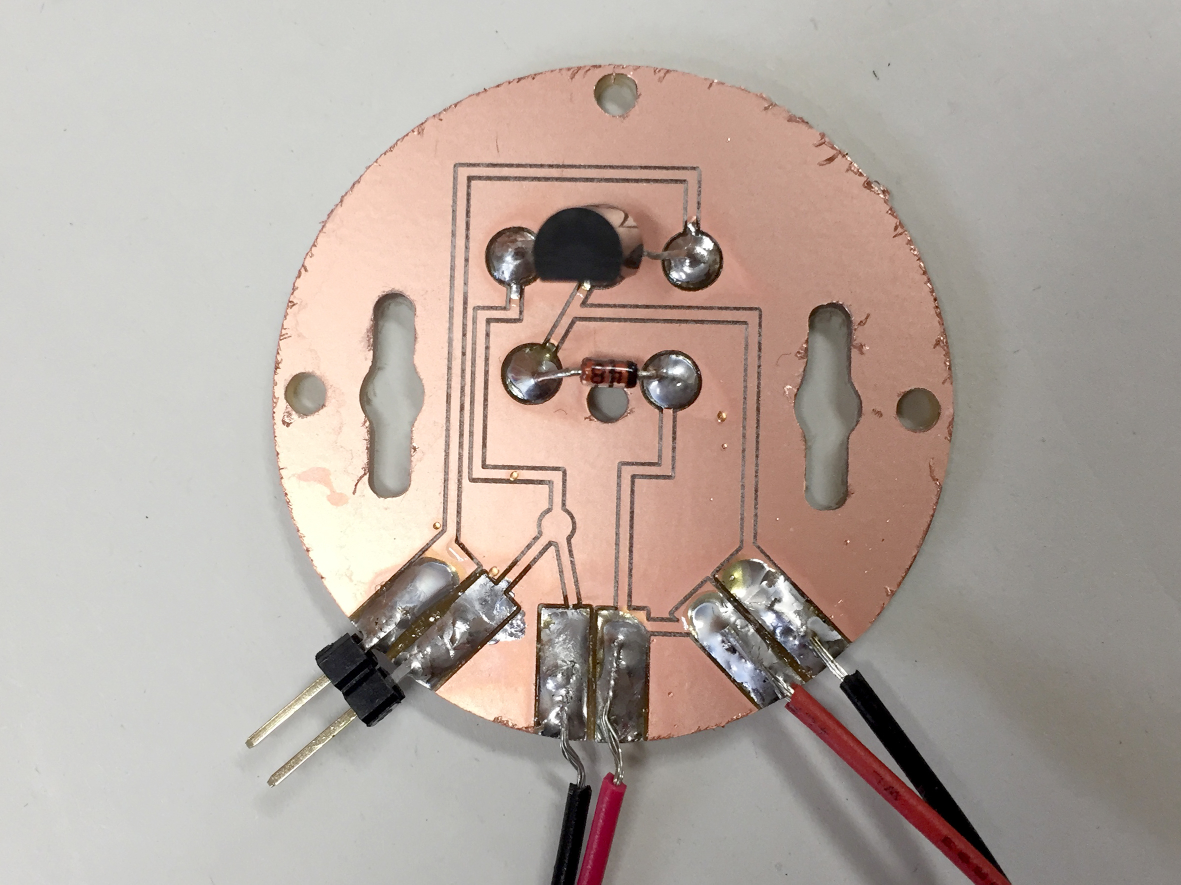
What you need for a motor
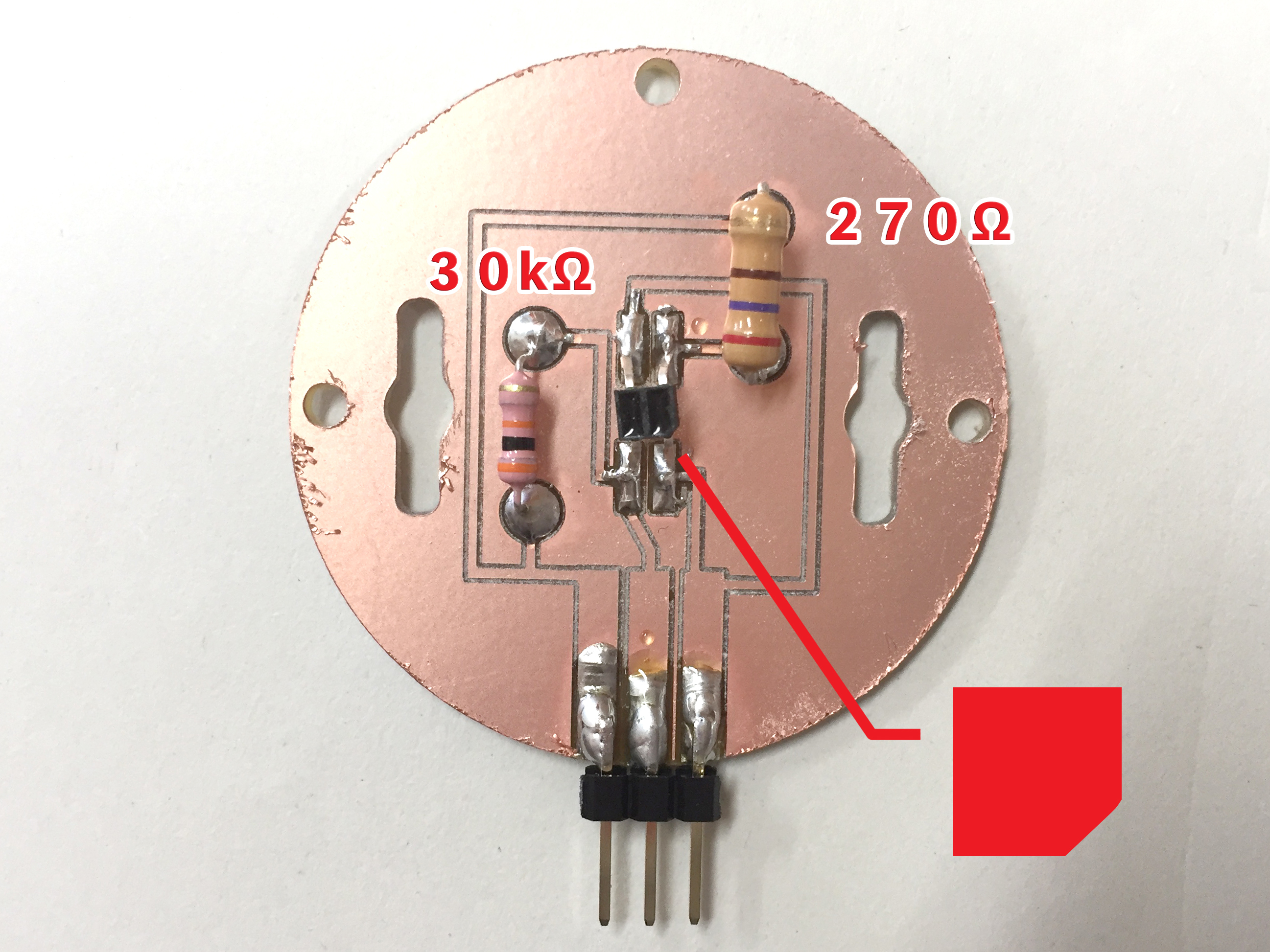
Please solder the transistor to the blue part, the diode to the orange and the pin header to the three vertical black parts.
Connect to MESH GPIOtag
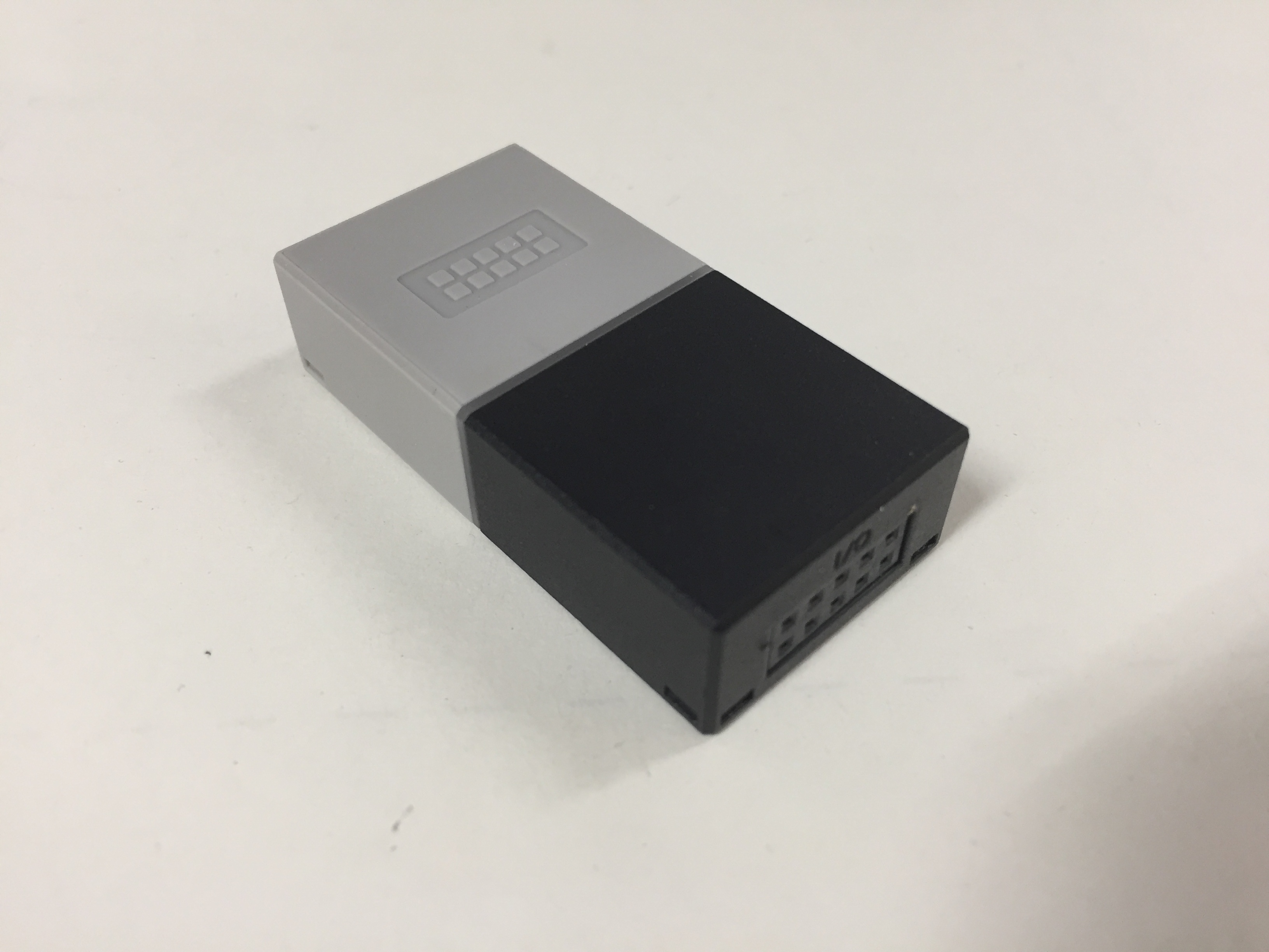
MESH GPIOtag is IoT tag which developed by SONY.
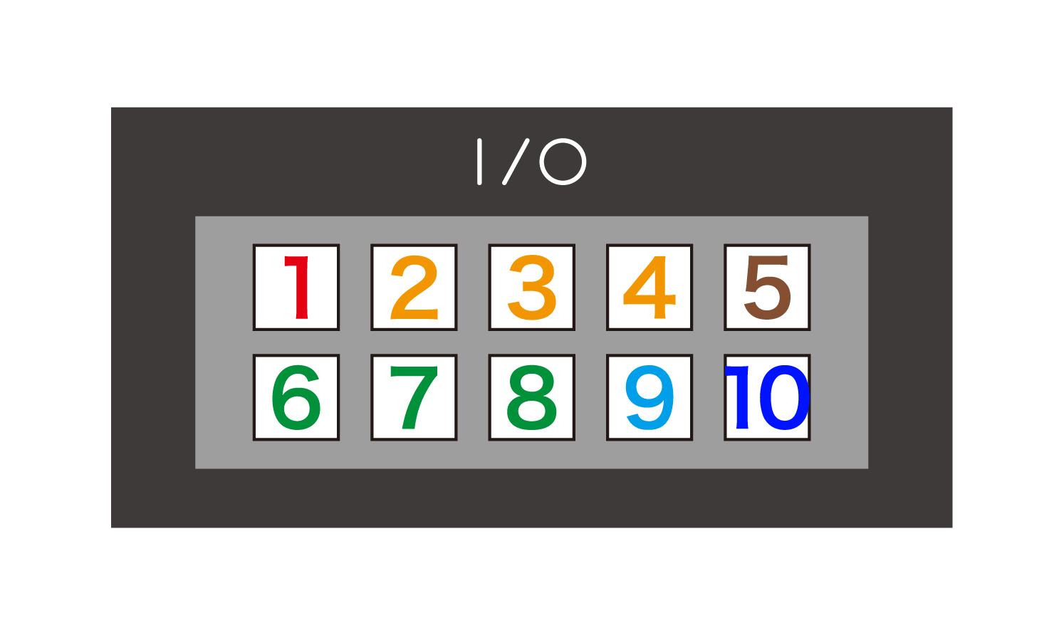
Each pin has a function.
Each pin has a function.
1:Power Out
2~4:Digital Input
5:Ground
6~8:Digital Output
9:Analog Input
10:PWM Output
brightness sensor
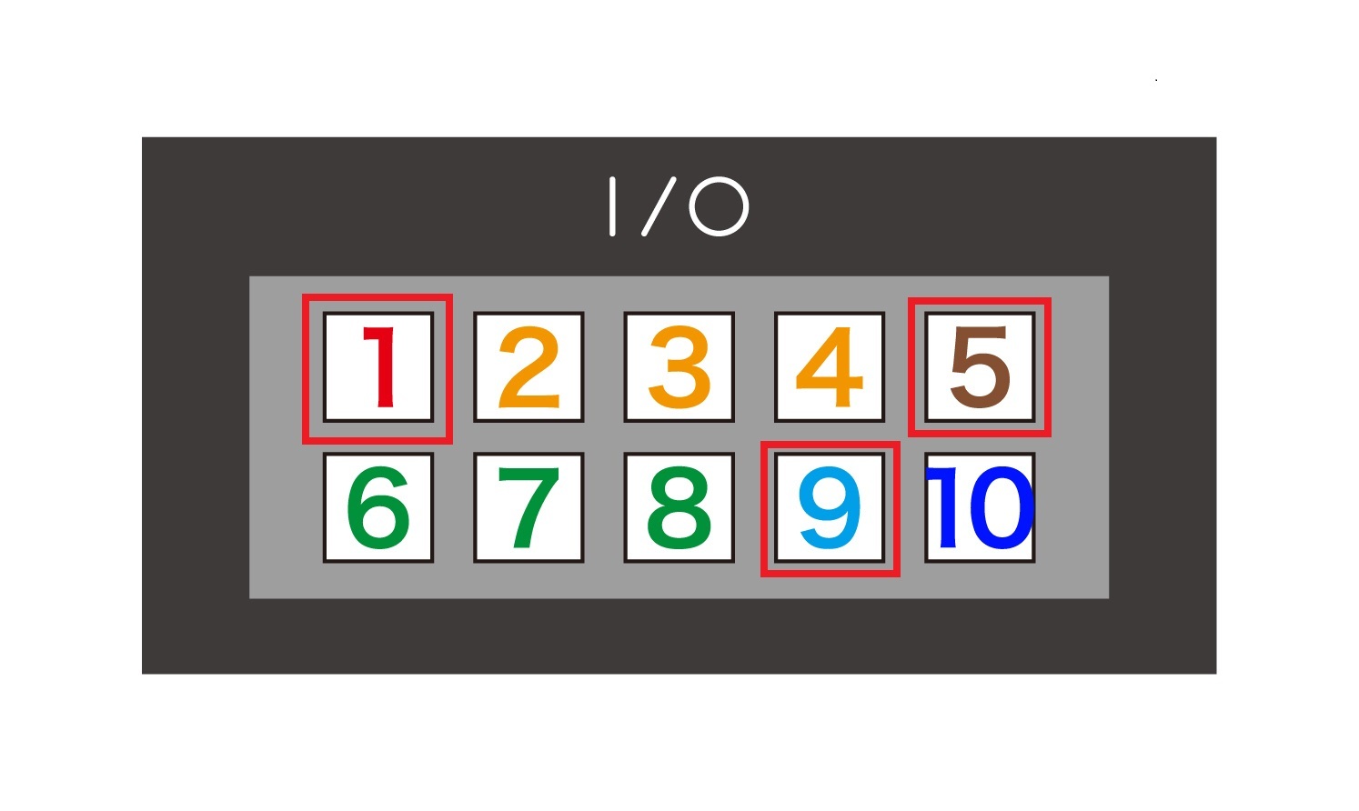
+→1(PowerOut)
−→5(Ground)
signal→9(AnalogInput)
−→5(Ground)
signal→9(AnalogInput)
pressure sensor

+→1(PowerOut)
−→5(Ground)
signal→9(AnalogInput)
−→5(Ground)
signal→9(AnalogInput)
short-range sensor

+→1(PowerOut)
−→5(Ground)
signal→9(AnalogInput)
−→5(Ground)
signal→9(AnalogInput)
LED
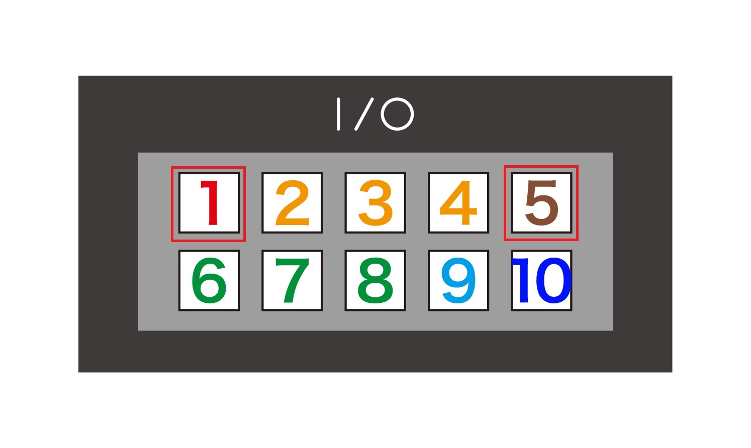
+→1(PowerOut)
−→5(Ground)
−→5(Ground)
motor(relay swich)

+→1(PowerOut)
−→5(Ground)
−→5(Ground)
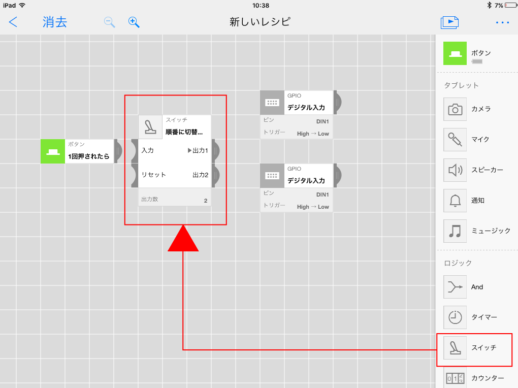
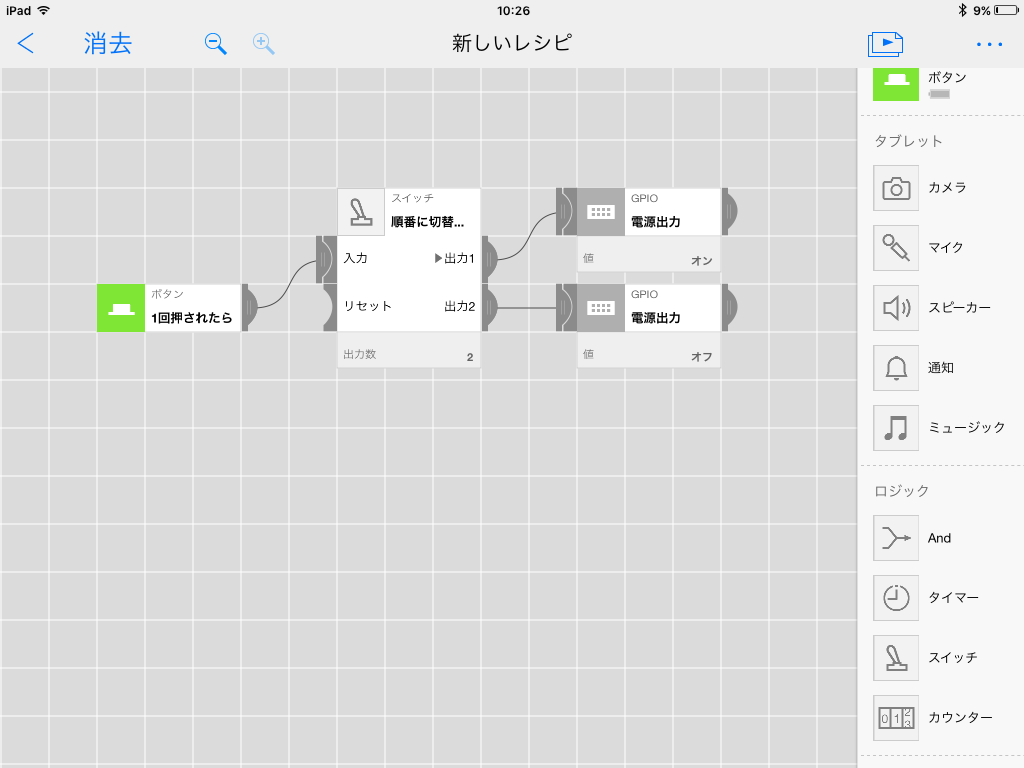
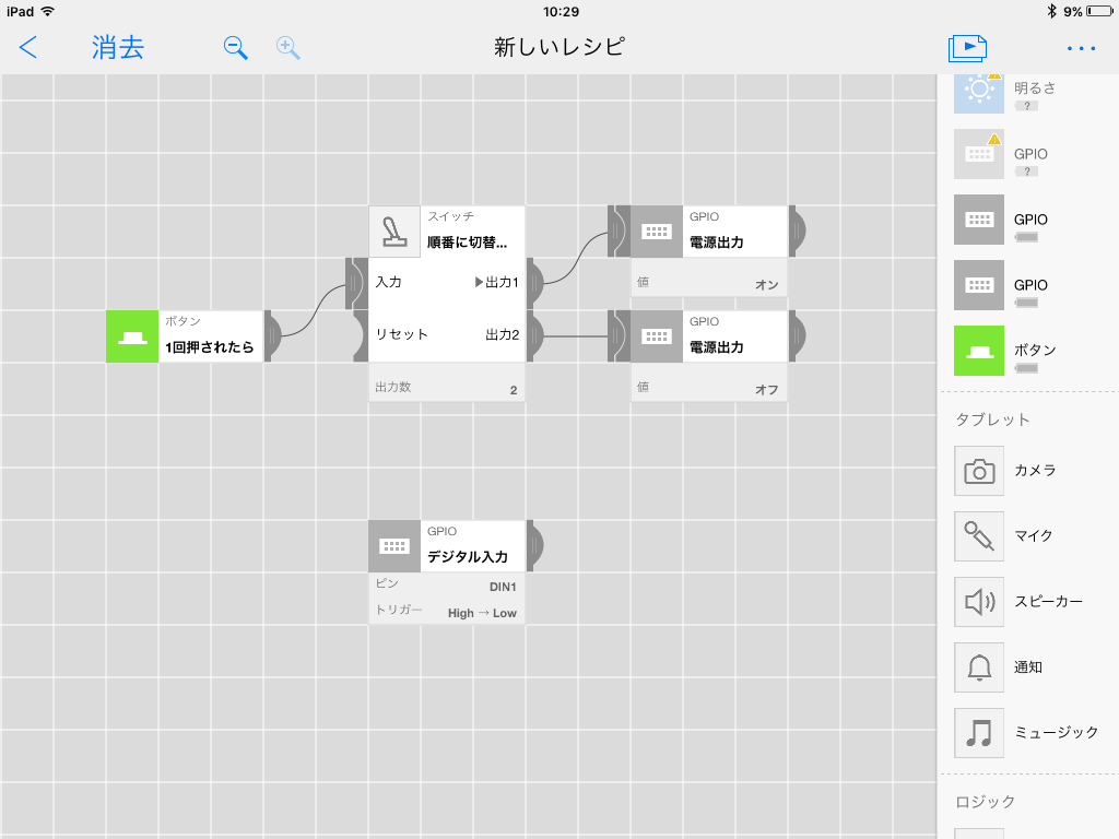
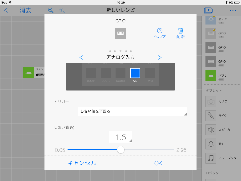
MESH
This is an example, that responds to the sensor and sounds a sound, of trying to check if the sensor functions properly.
Place GPIO Tag
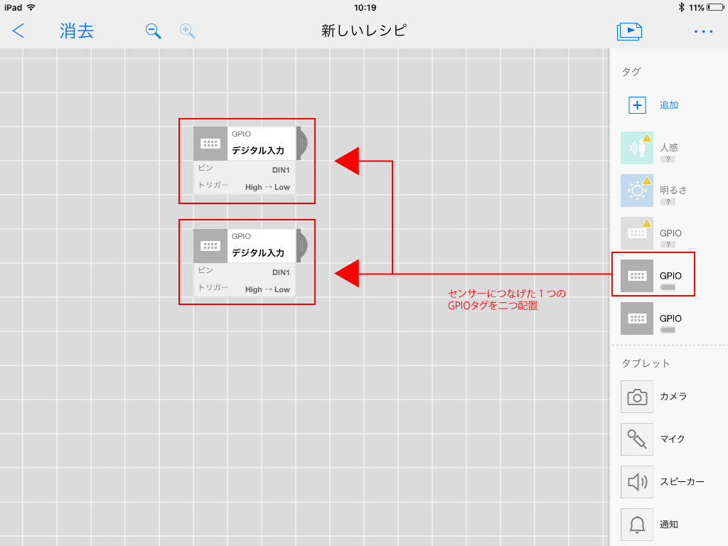
Place Button Tag
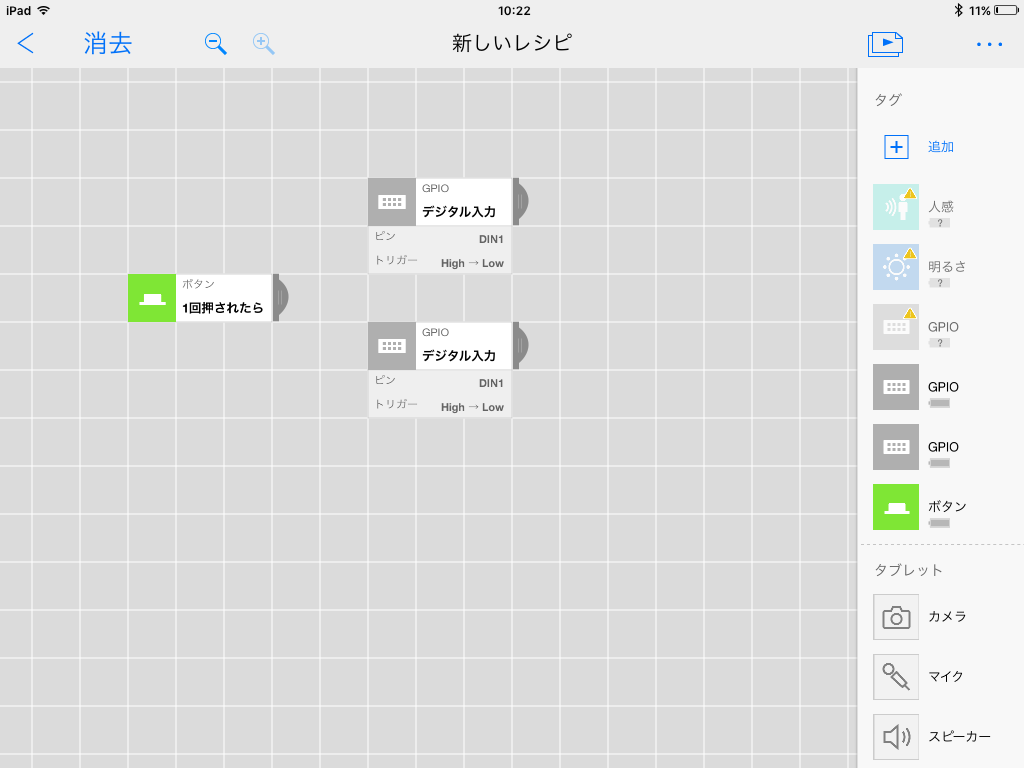
Place Swith Tag
Set the Power Out of the GPIO tag to ON
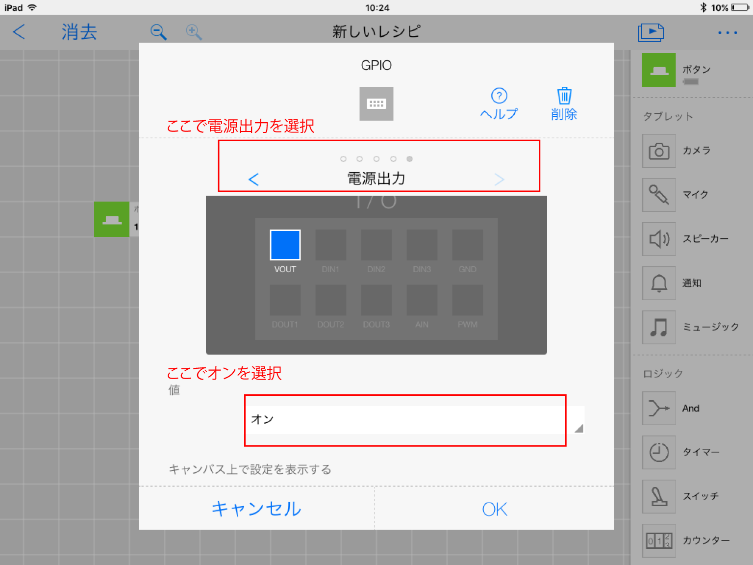
Set the Power Out of the GPIO tag to OFF
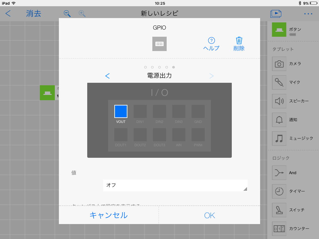
Connect
Place another GPIO Tag
Set Analog Input of GPIO Tag
Place Speaker Tag
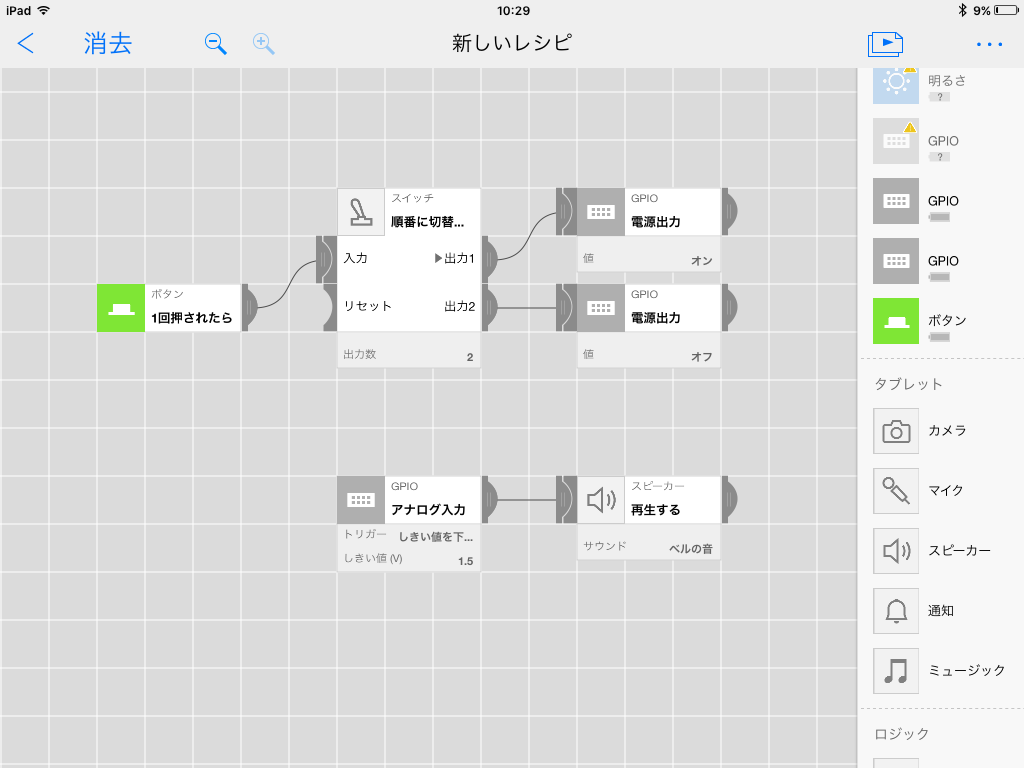
ex) MESH Recipe
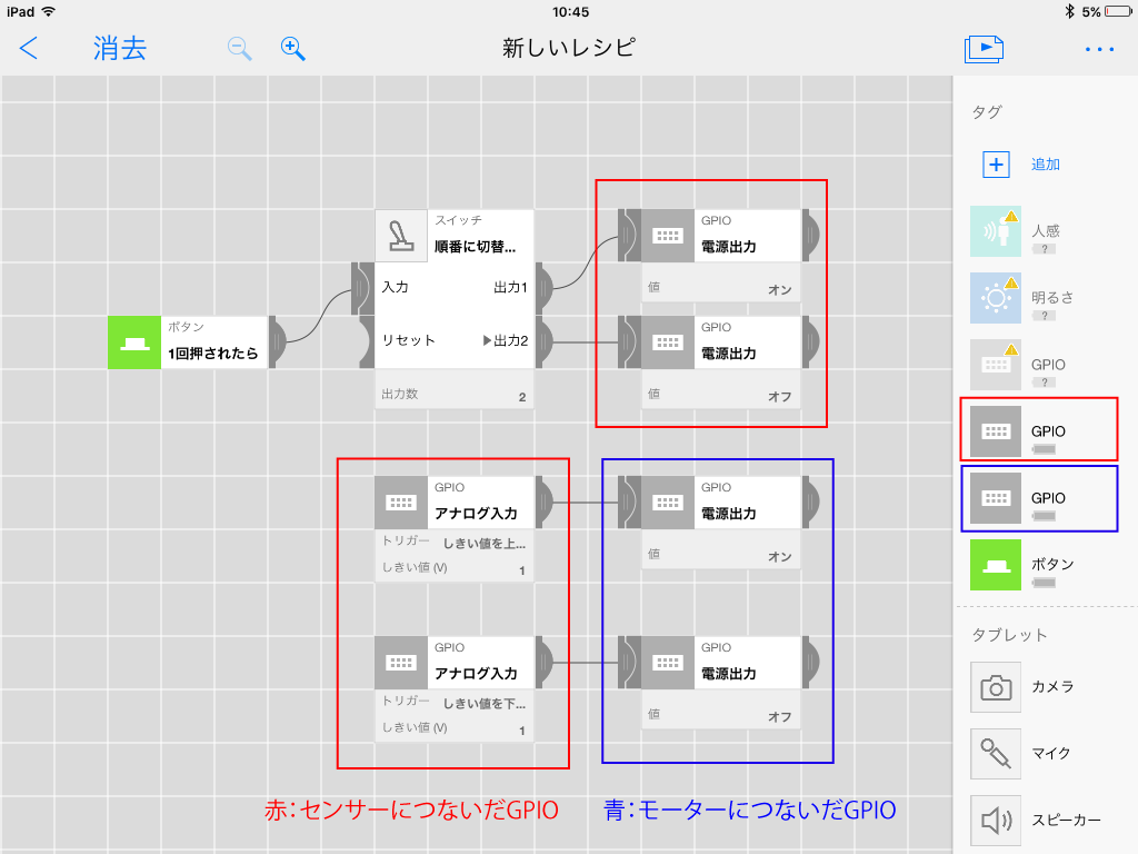
This is an example of connecting the brightness sensor and the motor.
One button tag
Two GPIO tags (for brightness sensor, motor)
One button tag
Two GPIO tags (for brightness sensor, motor)
Adaptation
Let’s adapt LED substrate you have produced to your life or hobby !
Acrylic cover
You have more choices for adaptation with an acrylic cover.
Download acrylic cover data and take an acrylic board to a place like Fablab where you can use a laser cutter.
You can make an acrylic cover with the downloaded data.
Use M2 screws and nuts to fix.
Download acrylic cover data and take an acrylic board to a place like Fablab where you can use a laser cutter.
You can make an acrylic cover with the downloaded data.
Use M2 screws and nuts to fix.
for CdS, LED
for mortor, short-ditance sensor
for pressure sensor
Let’s share !
Let’s share productions you make with AdaptationBoard in Usages !