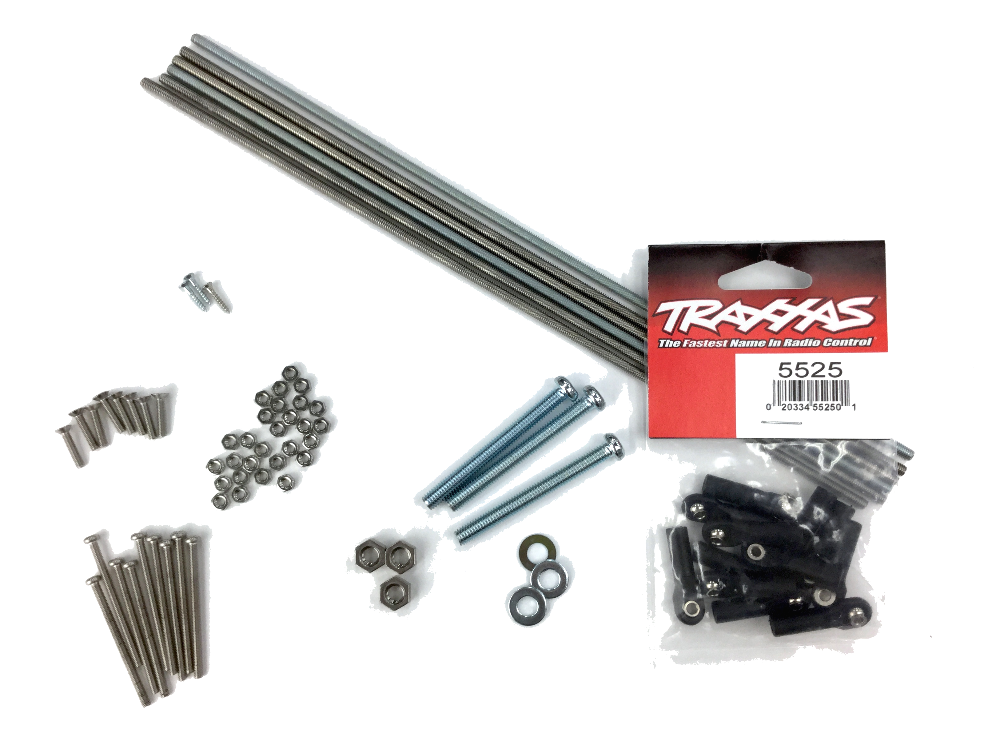
Materials 1/3 : Screws
MDF board (4mm 600*450mm) *1
Rod ends (TRAXXAS #5525 12 pieces)*1
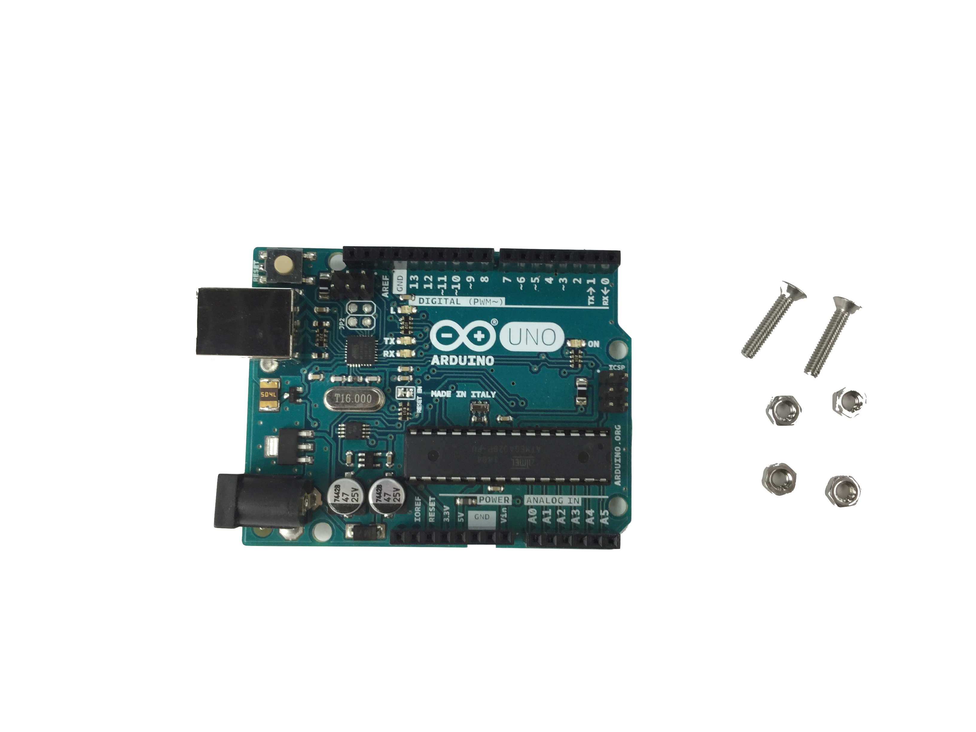
[Screws]
M2.1 Wood 13mm *3
M3 Flat-head 15mm *8
M3 Pan-head 45mm *9
M3 Nuts *34
M4 Threaded rods 285mm *6
M6 Pan-head *3
M6 Nuts *3
M6 Washers *3
Rod ends (TRAXXAS #5525 12 pieces)*1
[Screws]
M2.1 Wood 13mm *3
M3 Flat-head 15mm *8
M3 Pan-head 45mm *9
M3 Nuts *34
M4 Threaded rods 285mm *6
M6 Pan-head *3
M6 Nuts *3
M6 Washers *3
Materials 2/3 : Electronic Parts
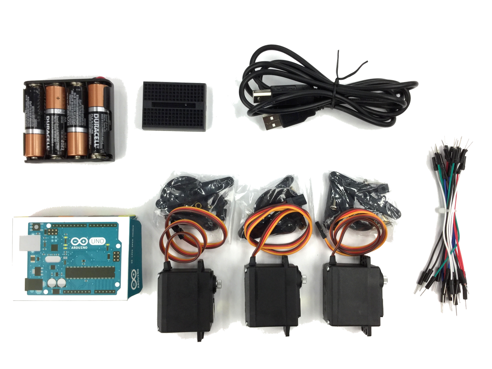
Servo motors MG995/996 *3
Arduino Uno *1
USB cable (A to B Male/Male) *1
Mini breadboard *1
Battery box (4 AA batteries) *1
AA battery *4
Jump wires
Arduino Uno *1
USB cable (A to B Male/Male) *1
Mini breadboard *1
Battery box (4 AA batteries) *1
AA battery *4
Jump wires
Materials 3/3 : Tools
Computer (Win/Mac/Linux)
3d printer / Laser cutter
Plus Driver No.1
3d printer / Laser cutter
Plus Driver No.1
Long-nose pliers
Wood glue
Sanding paper (#100 or #150)1. Digital Crafting
Make some of the parts before assembling them.
1-1. 3d-printing
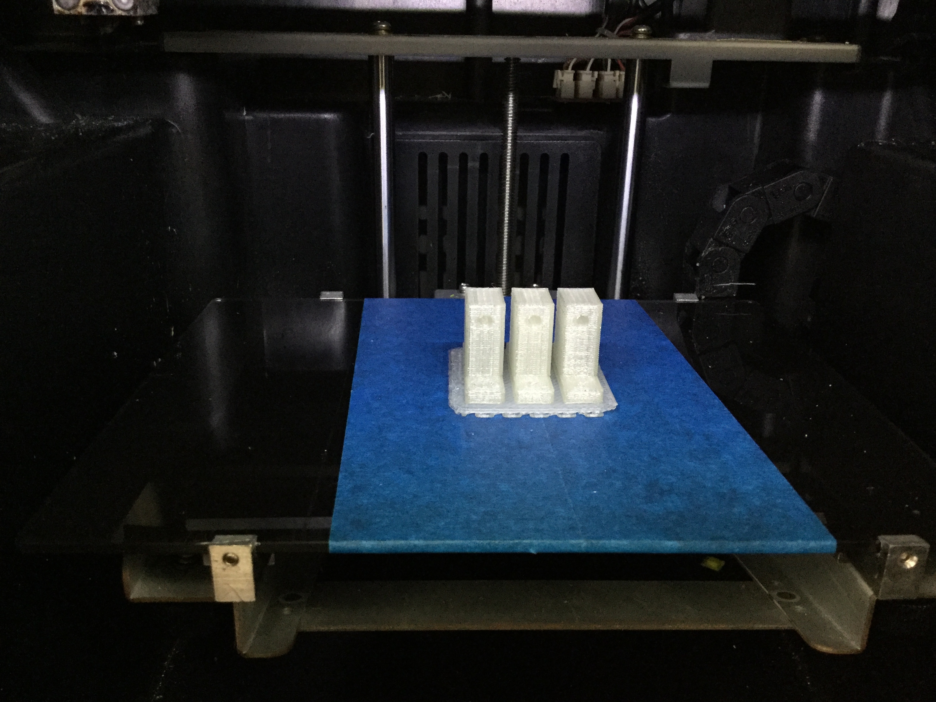
Make the joing parts that connects rods and the top board, using your 3d-printer.
Download and print this data below.
Download and print this data below.
1-2. レーザーカッター
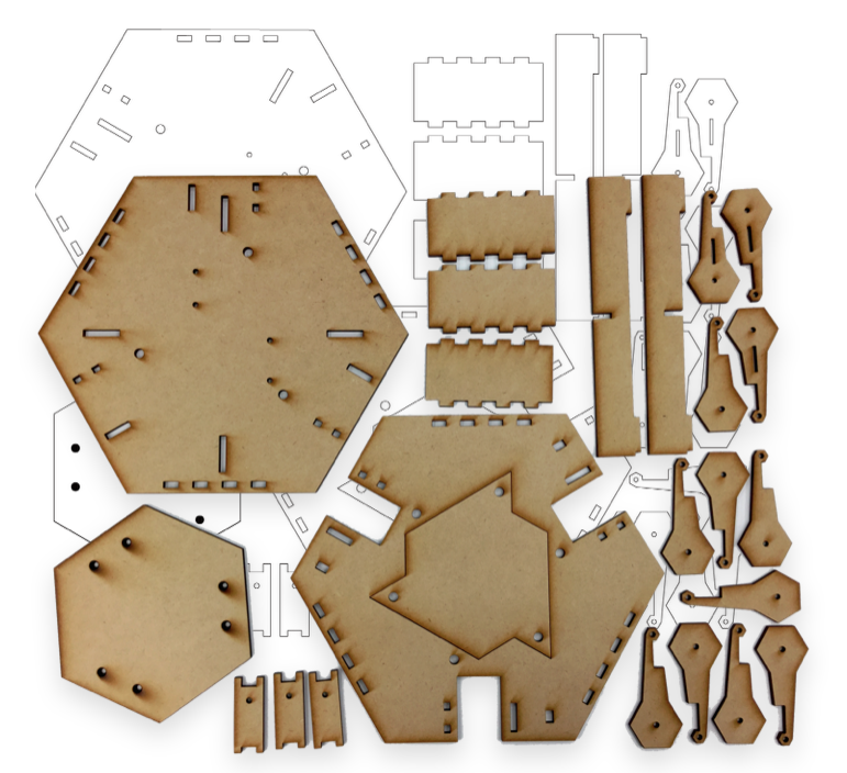
Laser-cut your MDF Board to make the most parts of the body of OCPC.
Download delta_16072801.ai and send it to your laser-cutter.
It would be best if you can engrave by 2mm for raster-drawing section.
Download delta_16072801.ai and send it to your laser-cutter.
It would be best if you can engrave by 2mm for raster-drawing section.
2. Hand Crafting (Gluing and Sanding)
Prepare the rest of parts.
2-0. Before glue things...
*Make sure to put things 100% straight
*Don't let the glue to reach the holes (except for rectangular holes)
Or your OCPC does not work well although you complete assembling it.
*Don't let the glue to reach the holes (except for rectangular holes)
Or your OCPC does not work well although you complete assembling it.
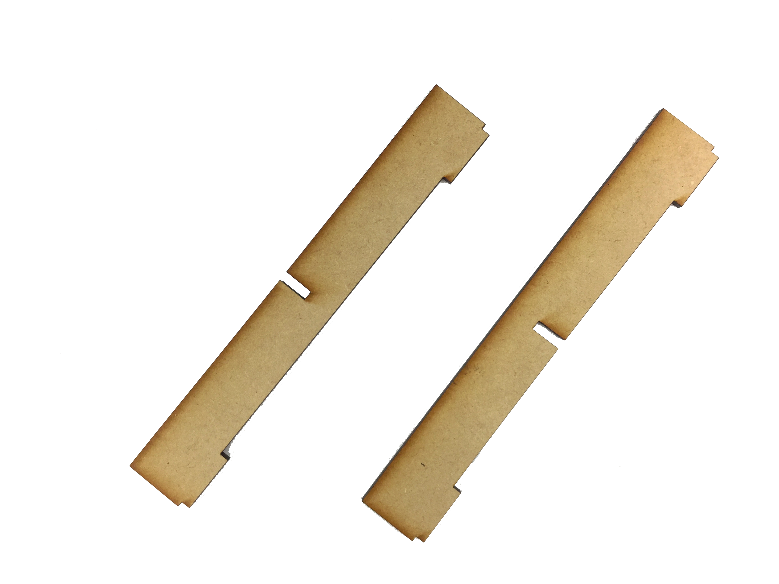
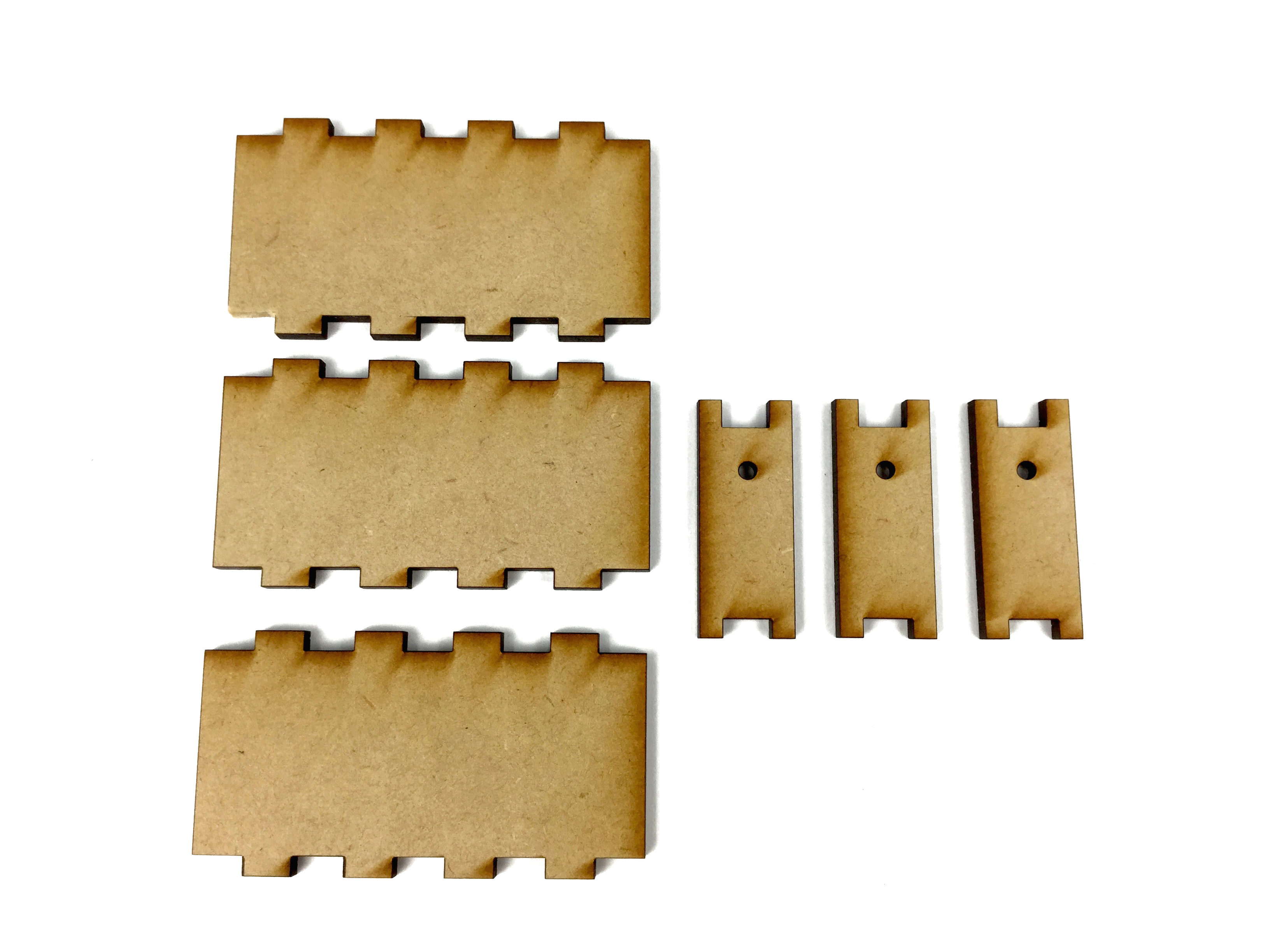
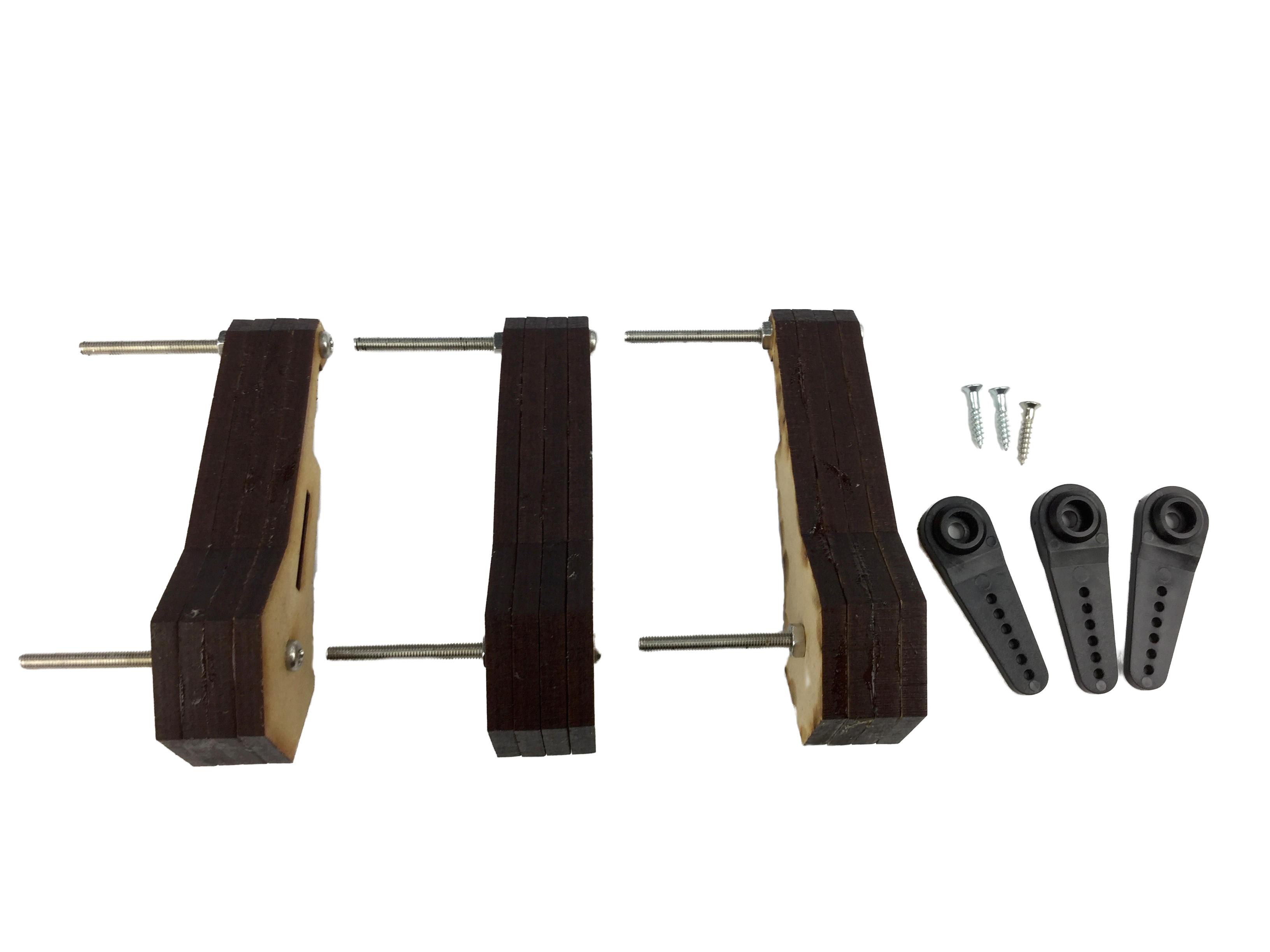
2-1. Gluing the arm parts 1/2
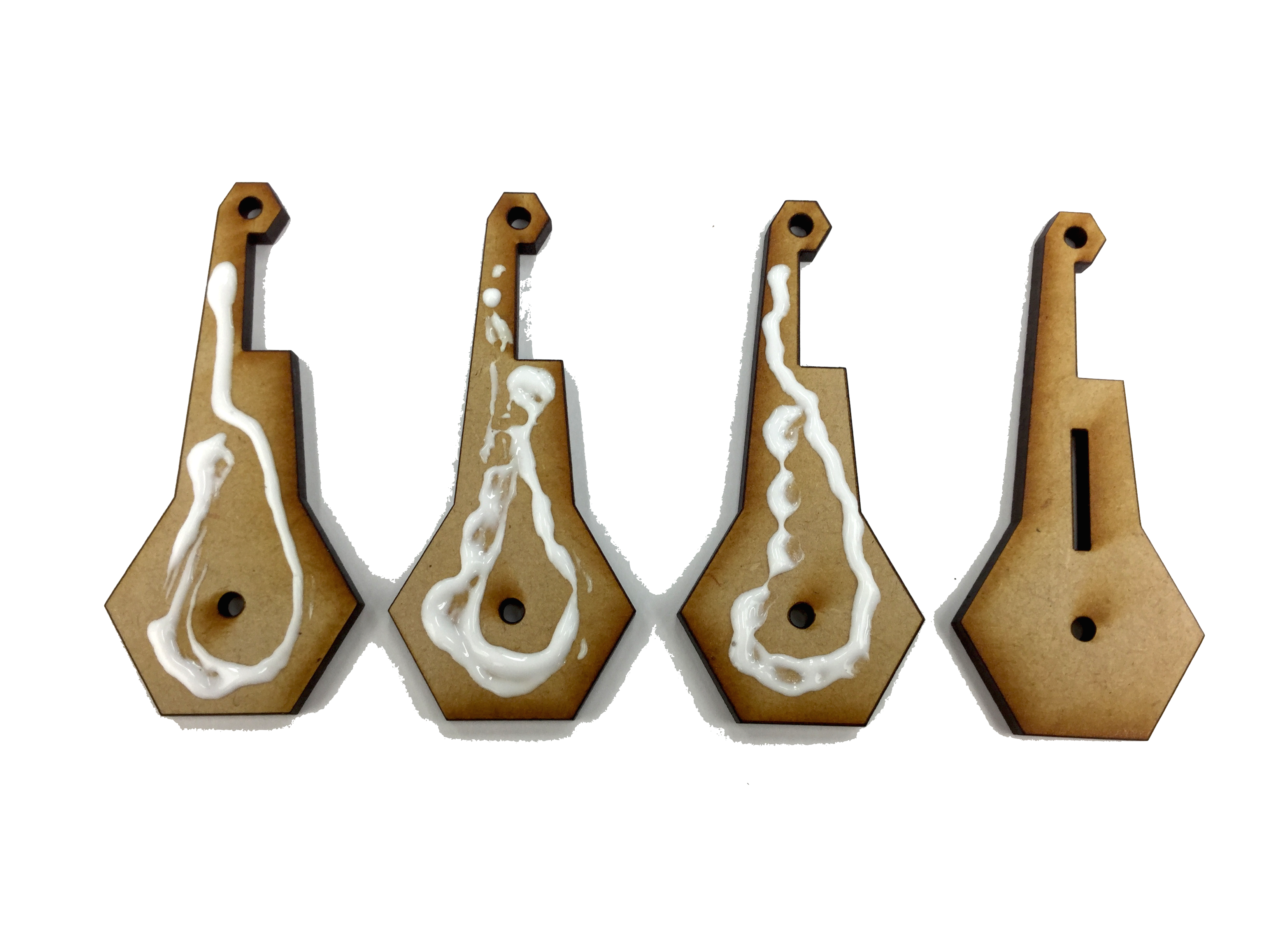
Glue the arm parts together with wood glue.
Pick one with a rectangular hole and three without rectangular holes. and glue them together as shown in picture.
Be careful not to glue them other way around.
Pick one with a rectangular hole and three without rectangular holes. and glue them together as shown in picture.
Be careful not to glue them other way around.
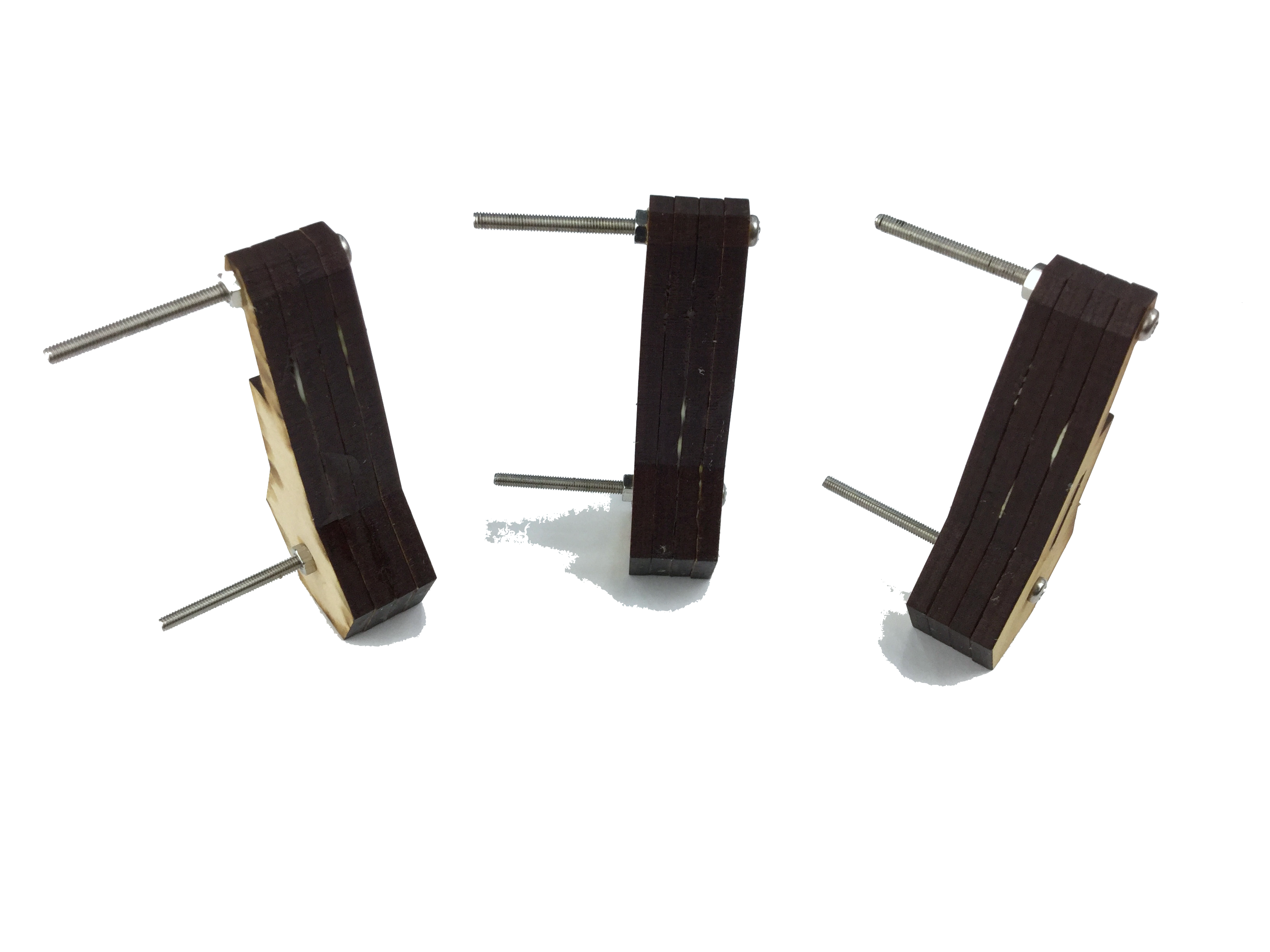
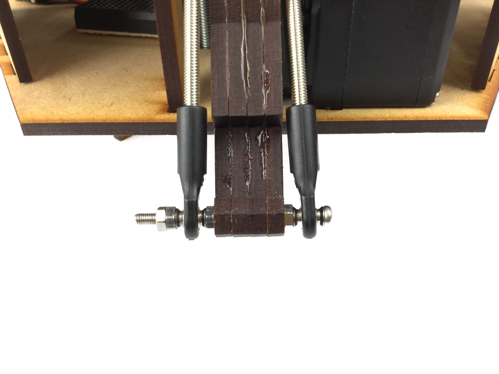
2-1. Gluing the arm parts 2/2
After putting the four parts together, pass M3 pan-head screws (45mm) through two round holes and tighten M3 nuts from the other side so that they don't move while waiting to dry.
Make sure to glue them super-neatly OR YOUR OCPC DOESN'T WORK WELL.
Make sure to glue them super-neatly OR YOUR OCPC DOESN'T WORK WELL.
2-2. Sanding
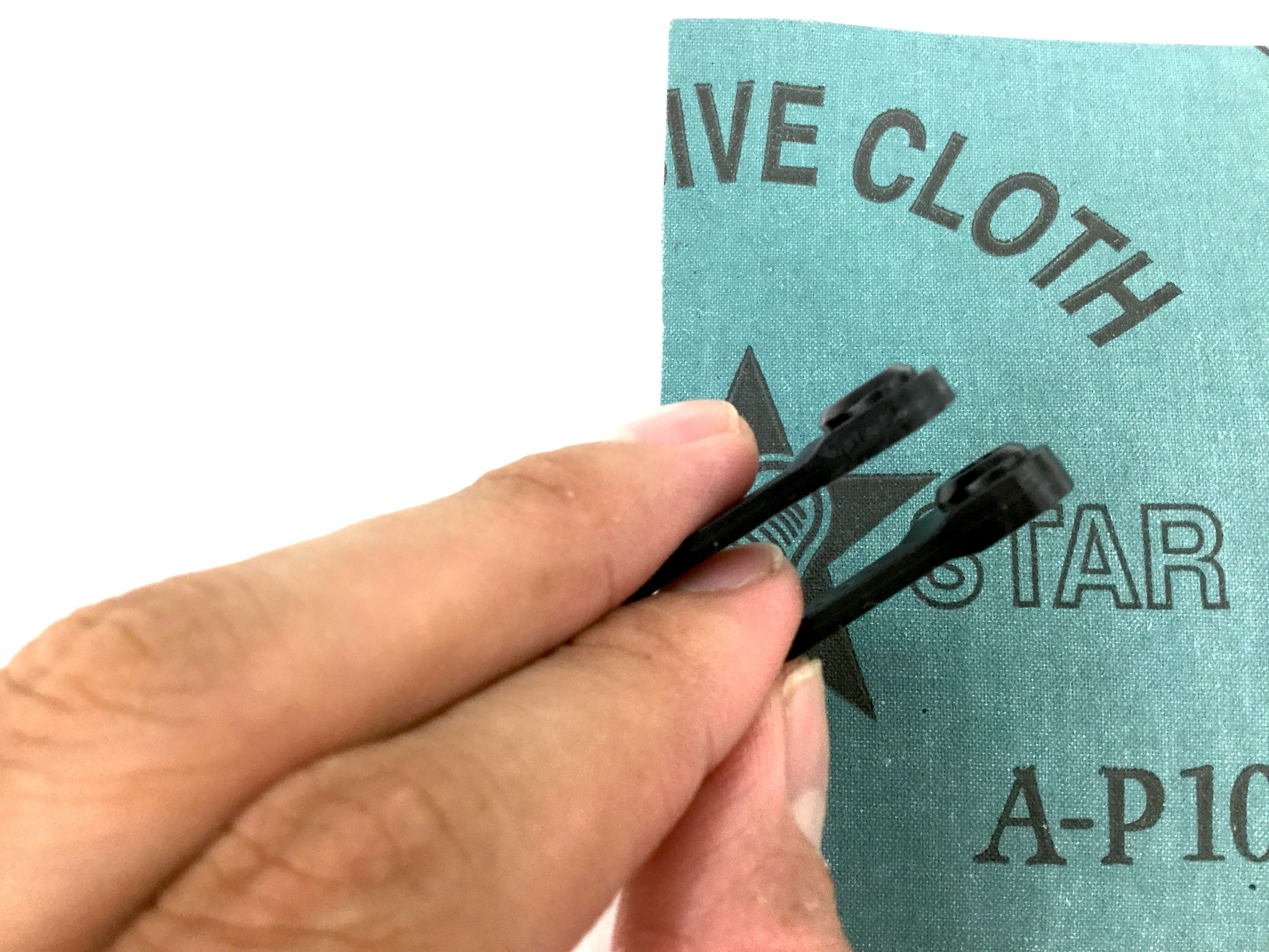
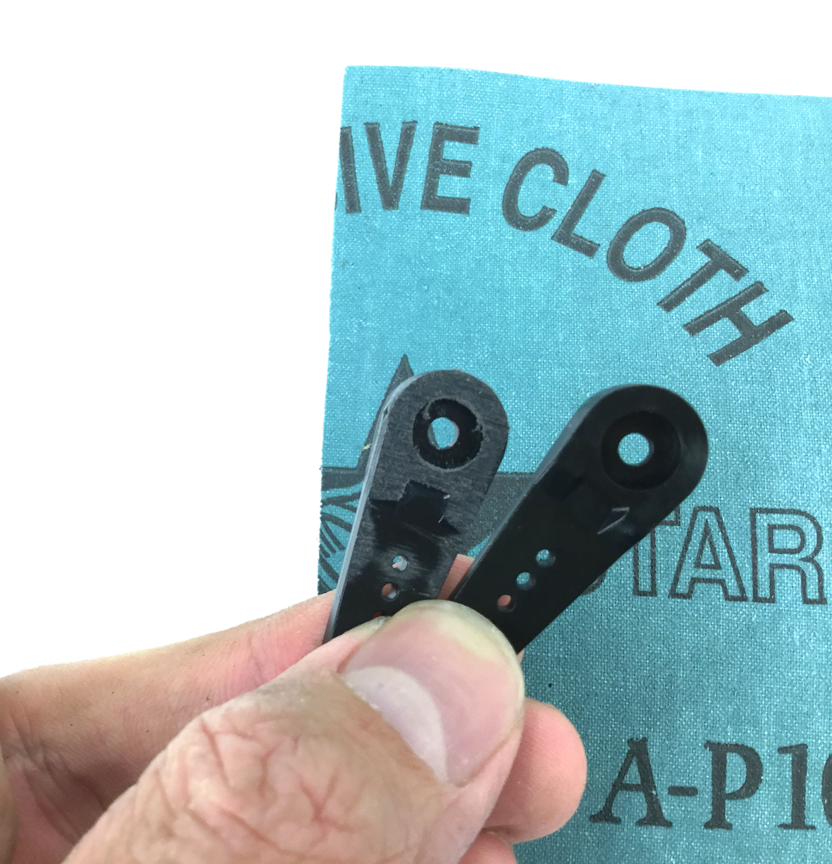
Sand the servo horns of MG995/MG996 to make flat, and to fit what we are making this time.
#100 or #125 sanding paper would be the best choice for it.
Because it is not very hard, make sure to stop sanding when it becomes flat and don't sand them too much.
#100 or #125 sanding paper would be the best choice for it.
Because it is not very hard, make sure to stop sanding when it becomes flat and don't sand them too much.
3. Assembling the body
Let's start assembling.
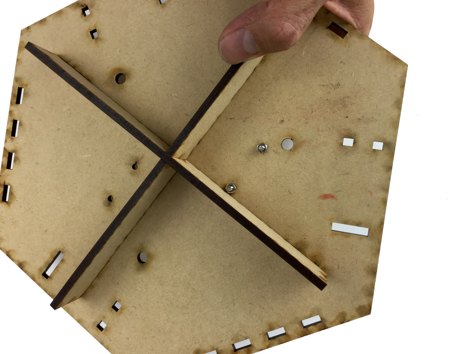
3-1. Assembling the Base 1/2
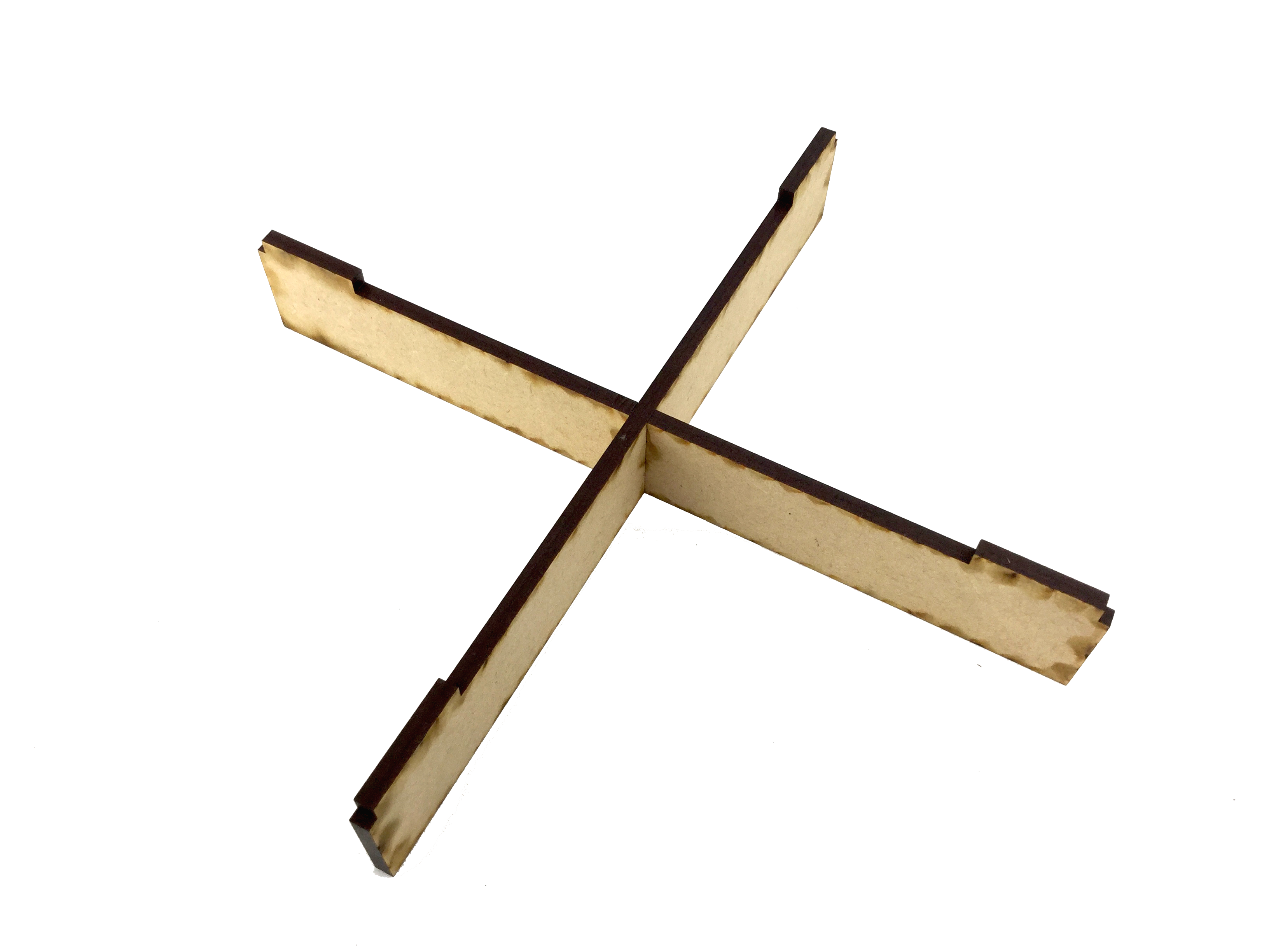
Pick the two long MDF parts (this will be the leg part) and assemble them as shown in picture.
Maybe you chould glue them with wood glue if they come off too easily.
Maybe you chould glue them with wood glue if they come off too easily.
3-2. Assembling the Base 2/2
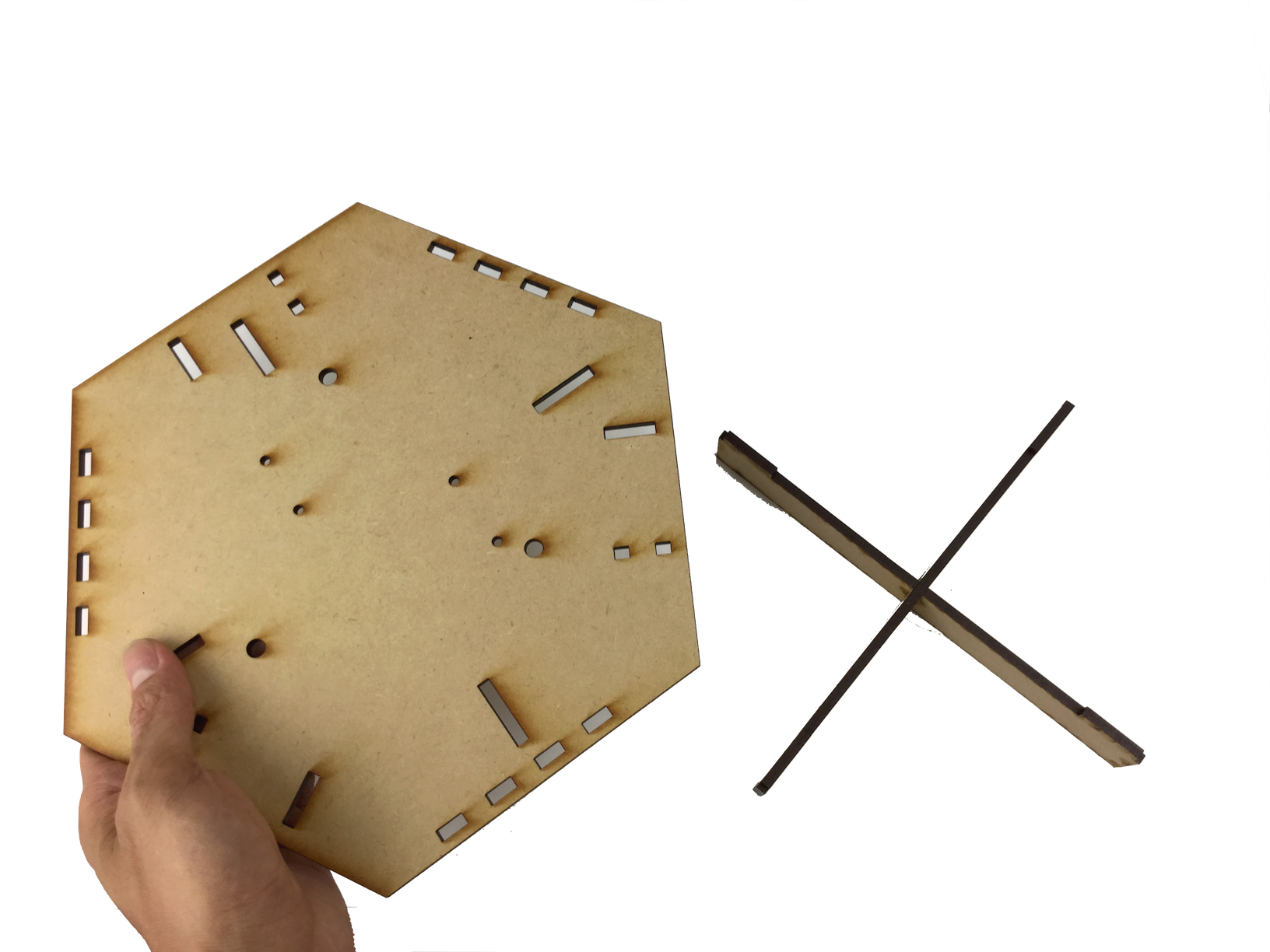
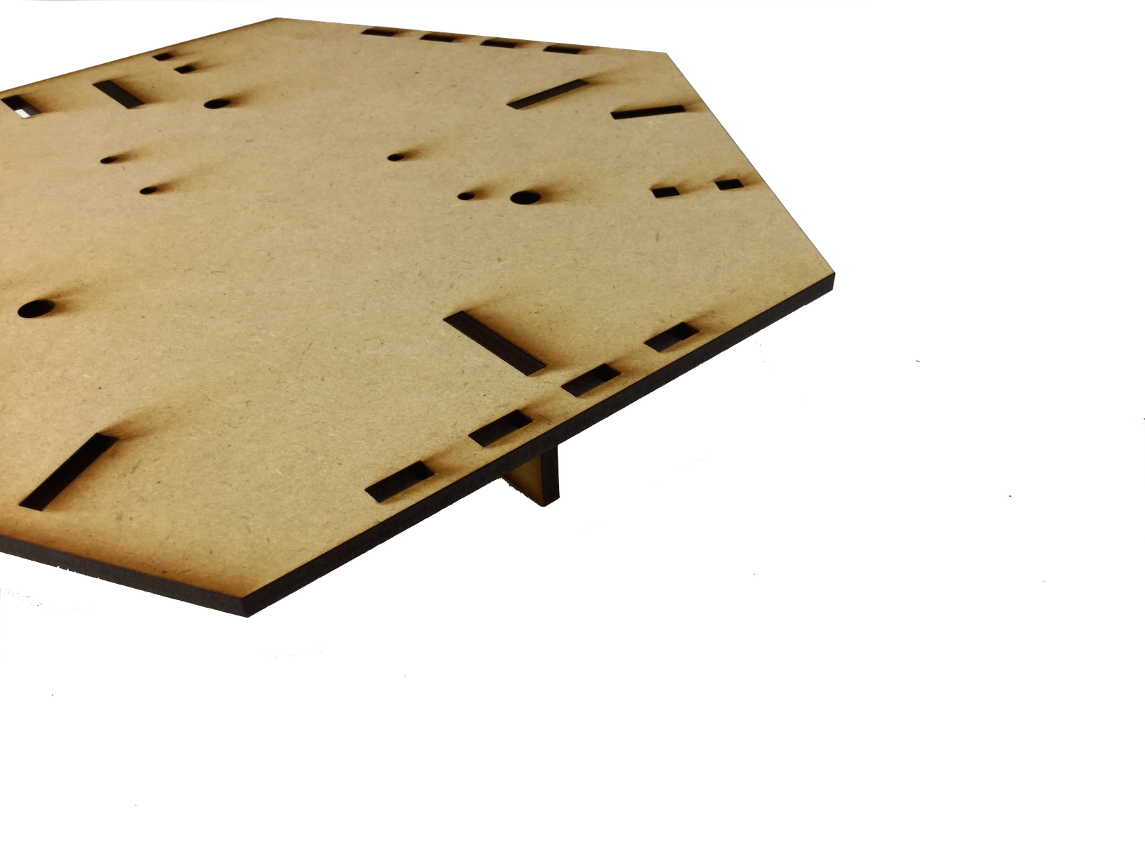
Pick the biggest MDF part (this will be the bottom part) and put together with the cross that you have just made.
Maybe you should glue them with wood glue if they come off too easily.
Maybe you should glue them with wood glue if they come off too easily.
3-3. Installing the Arduino (physically)
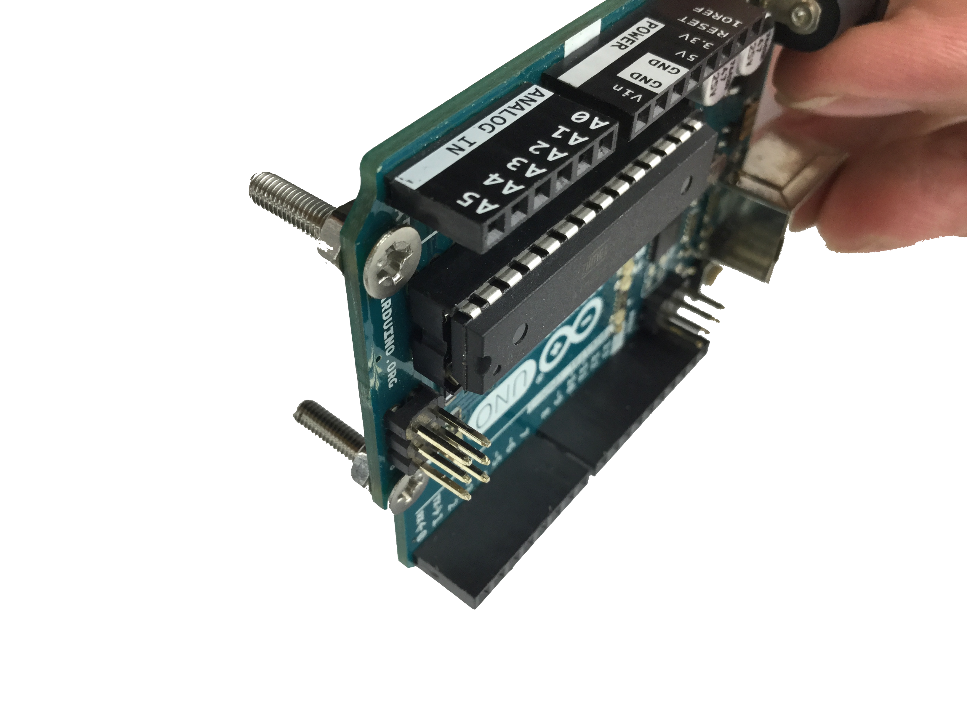
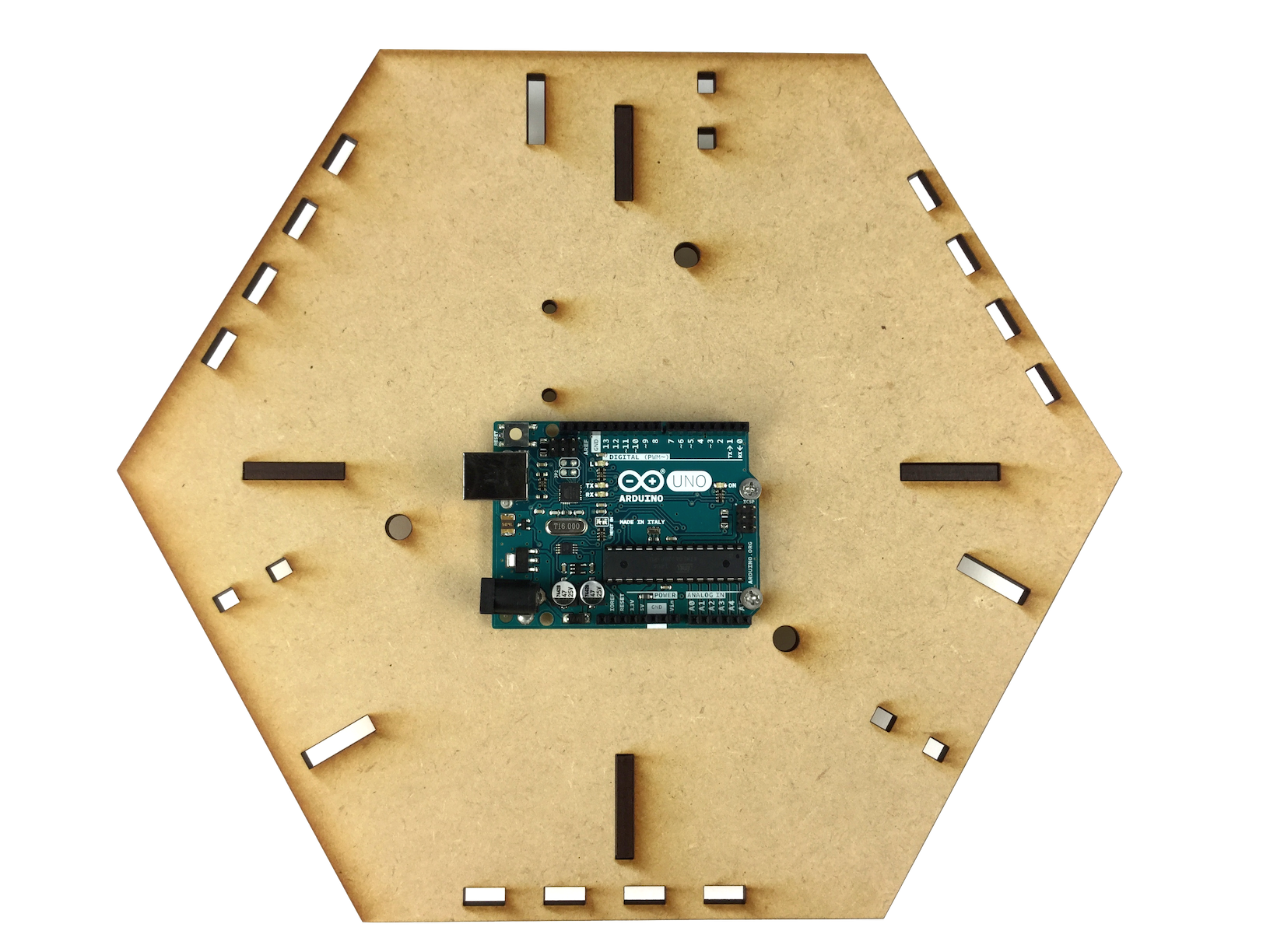
Pass M3 Flat-head screws (15mm) through two of the holes on Arduino, and tighten M3 nuts from the other side.
Then use two more M3 nuts to fix Arduino on the holes on the base plate.
Then use two more M3 nuts to fix Arduino on the holes on the base plate.
3-4. Installing the battery box and the breadboard
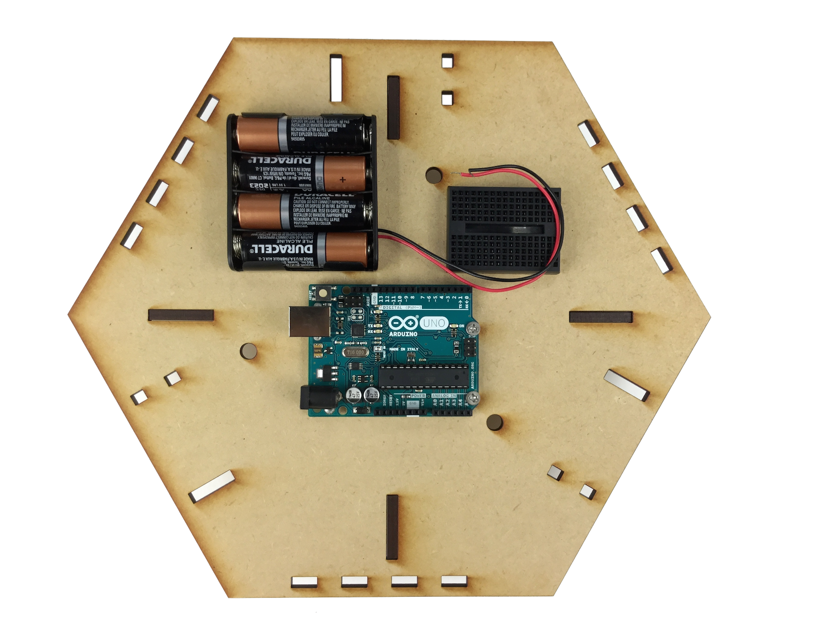
Fix the battery box and the mini breadboard as shown in picture.
Use double-sided tape to fix the battery box.
And the breadboard has adhesive tape on itself.
Don't fix them on the holes that you will use later.
Use double-sided tape to fix the battery box.
And the breadboard has adhesive tape on itself.
Don't fix them on the holes that you will use later.
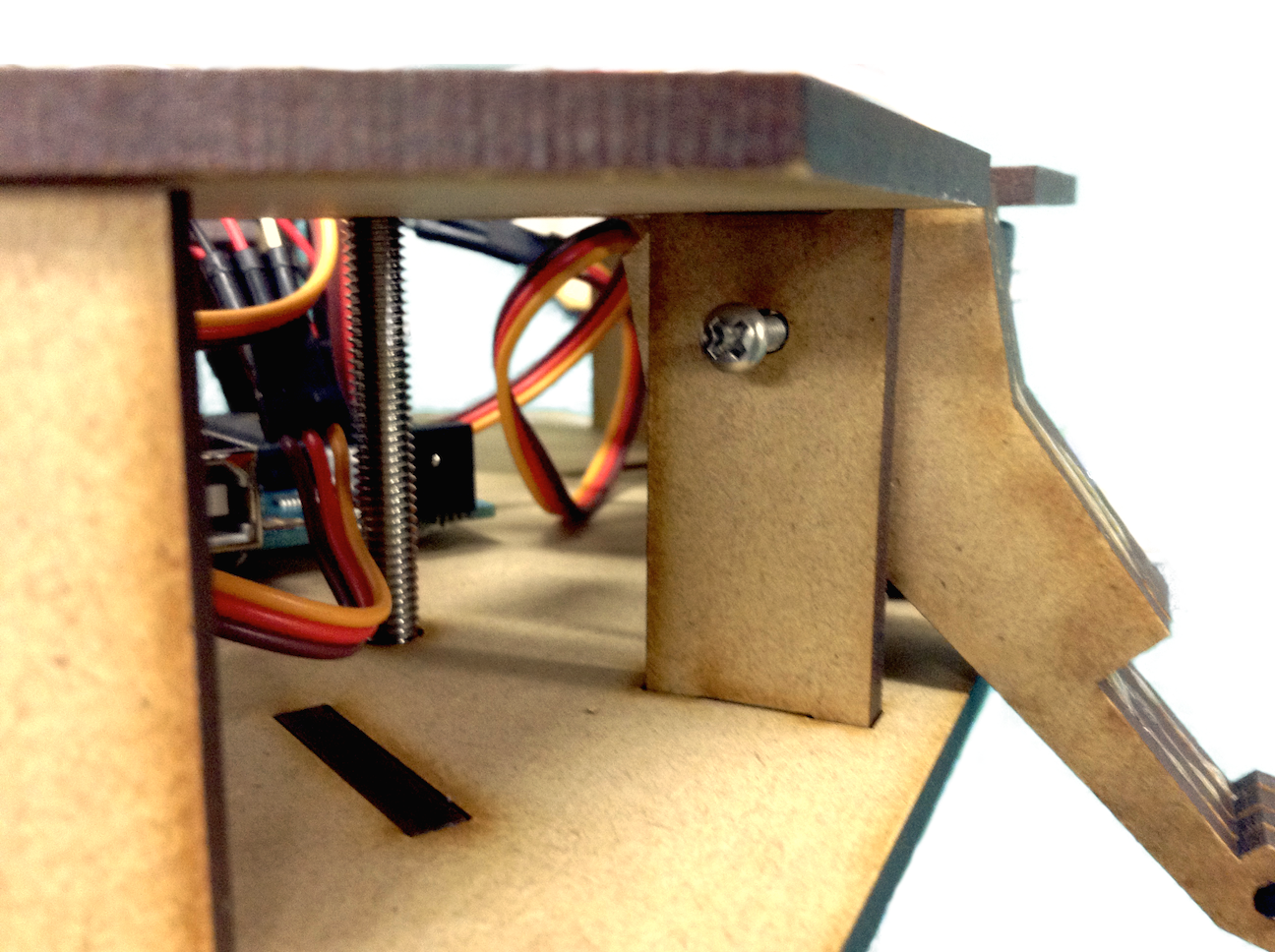
3-5. Putting vertical MDF parts
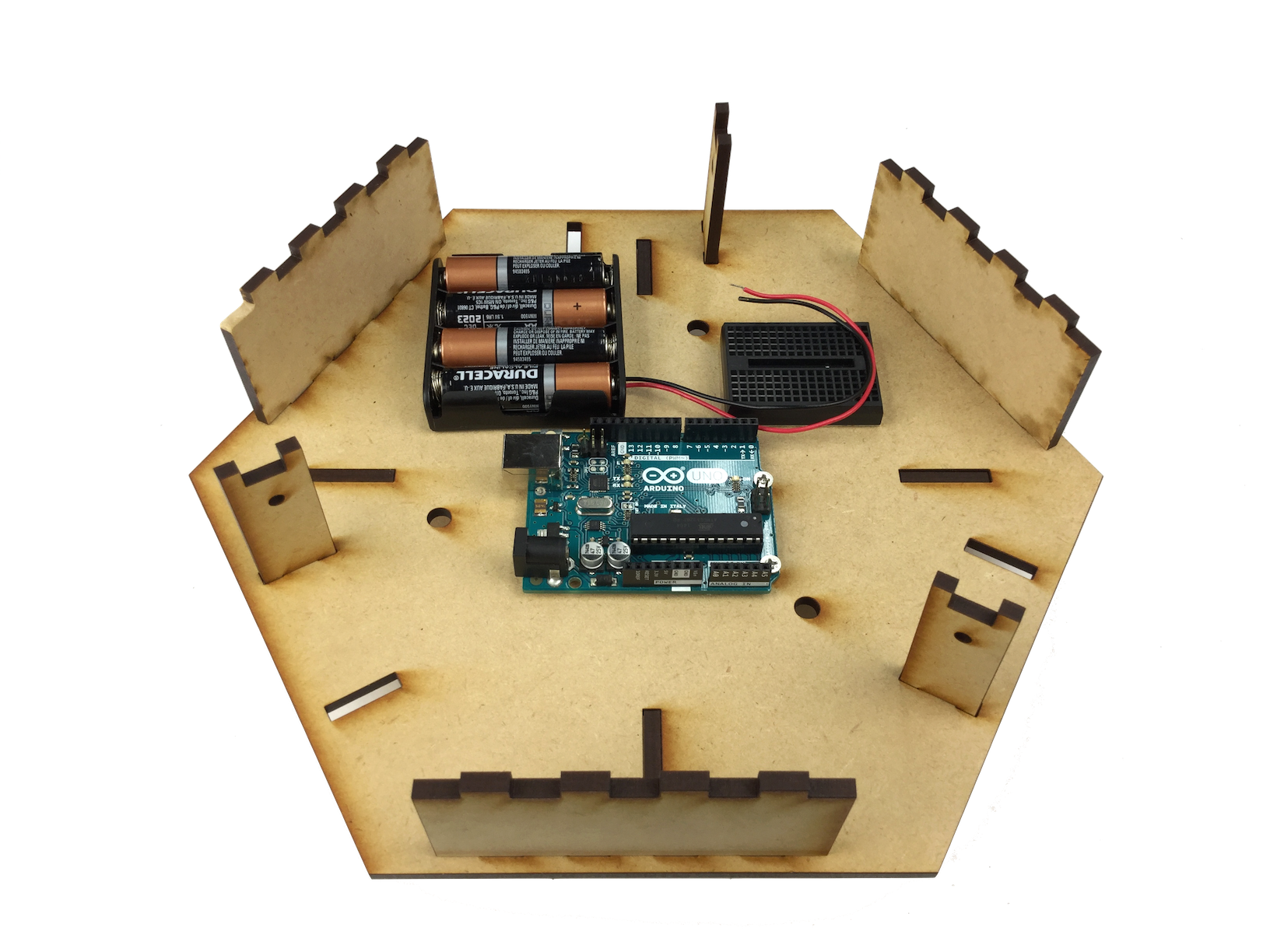
Put them together as they are shown in picture.
Notice that thinner one should have their holes on the upper half of them.
Notice that thinner one should have their holes on the upper half of them.
3-6. Putting Servos
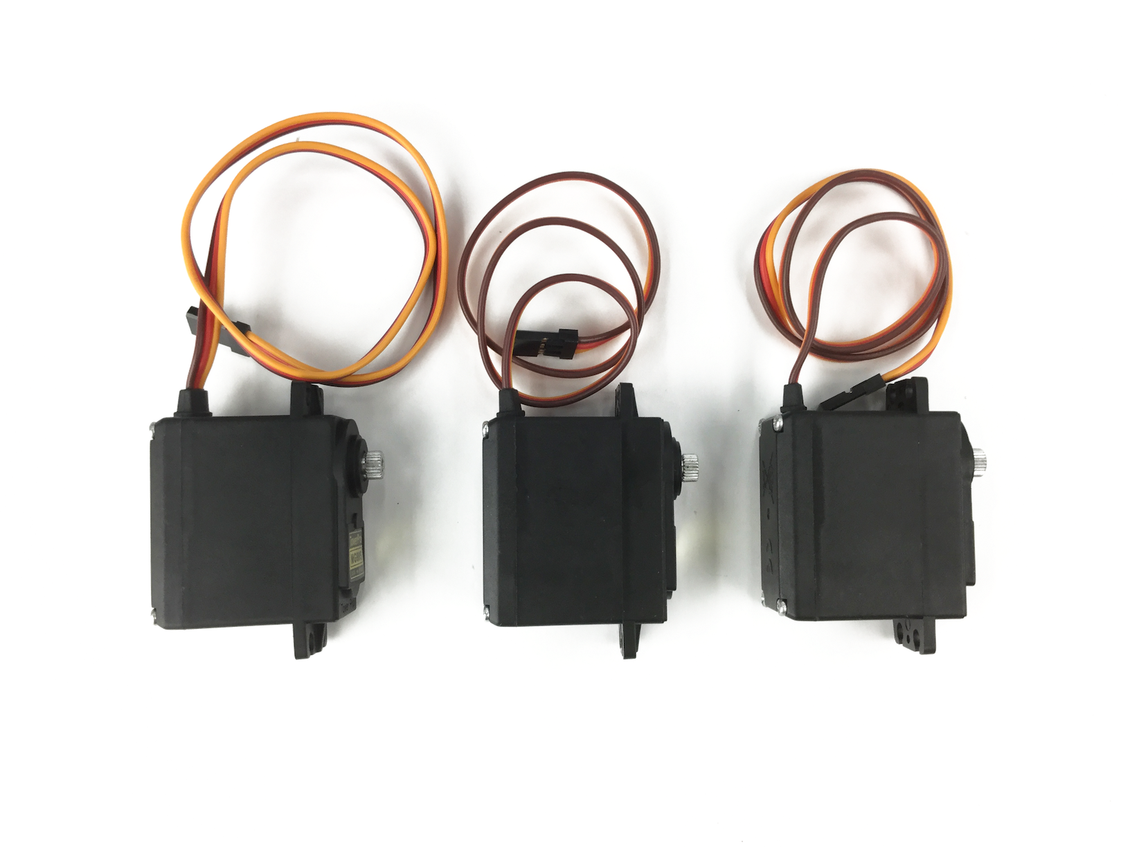
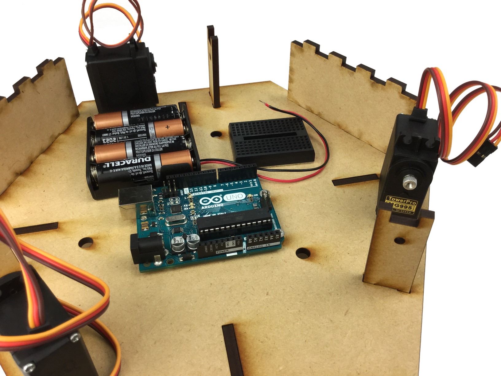
Pick three Servo motors (MG996/996) and put them on the rectangular holes of the base.
3-7. Putting the upper plate on
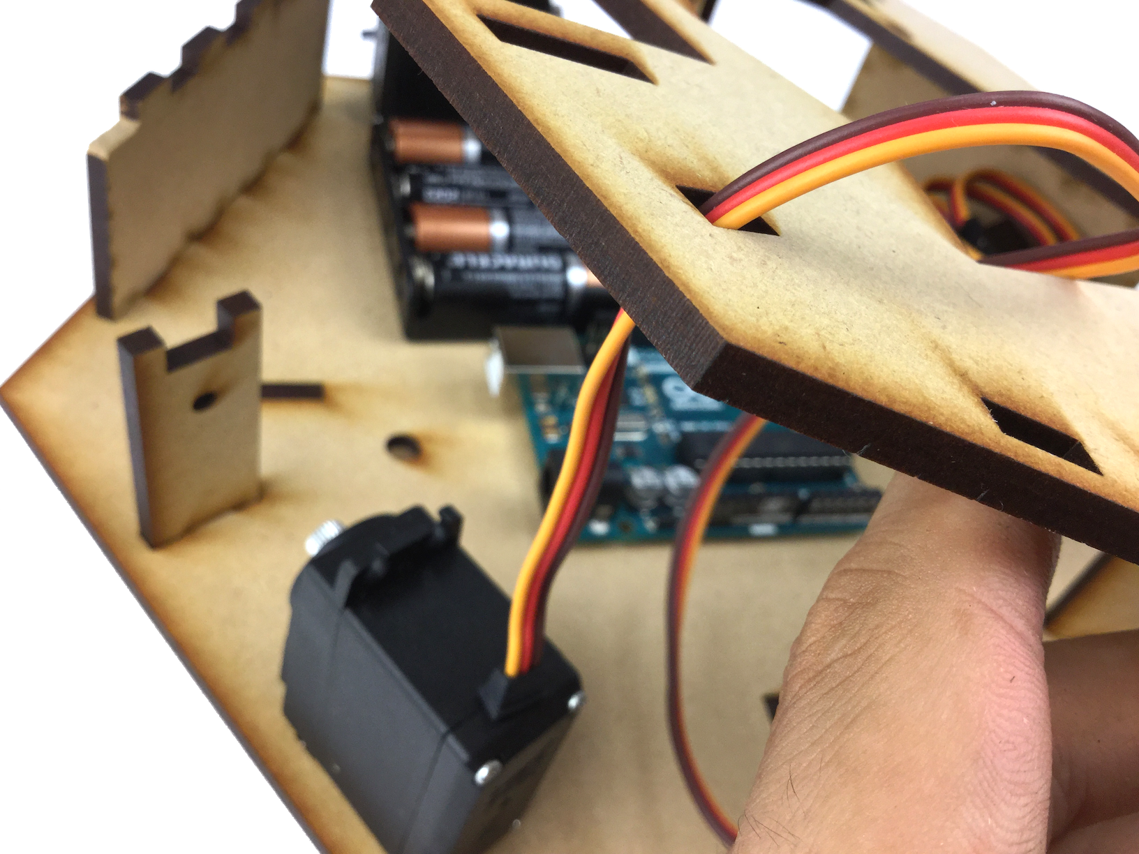
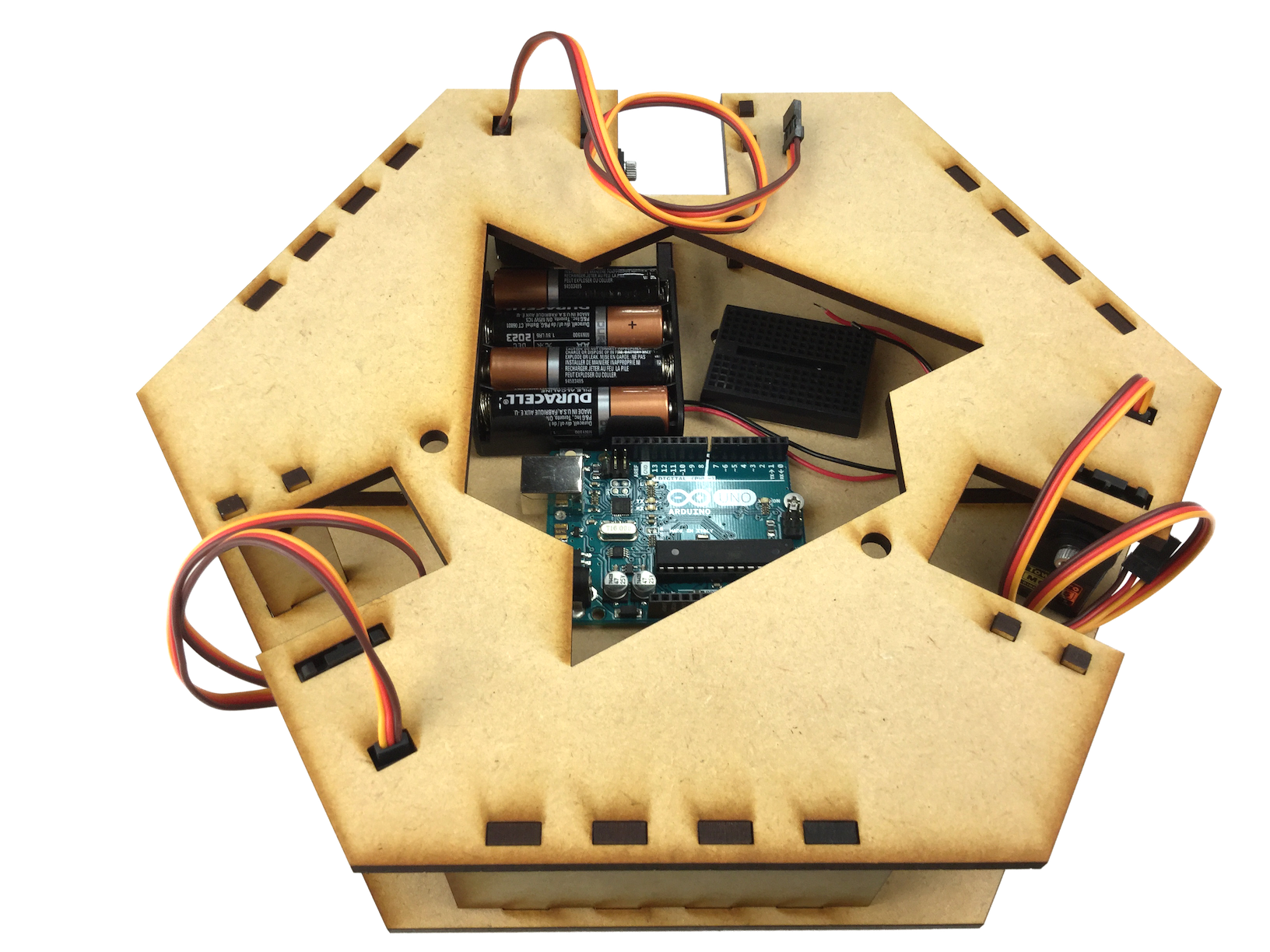
First, pass the wires of the servos through the corresponding holes on upper plate parts.
Then match all the shapes of vertical parts, upper plate and servos and put all the thing on together, at the same time.
You should fix them temporarily with M6 pan-head screws (60mm) if they come off easily.
Then match all the shapes of vertical parts, upper plate and servos and put all the thing on together, at the same time.
You should fix them temporarily with M6 pan-head screws (60mm) if they come off easily.
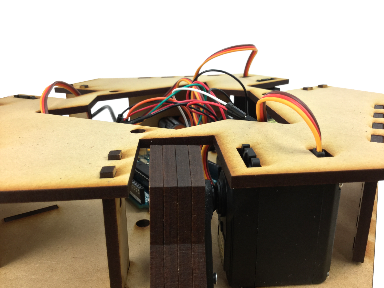
3-8. Wiring
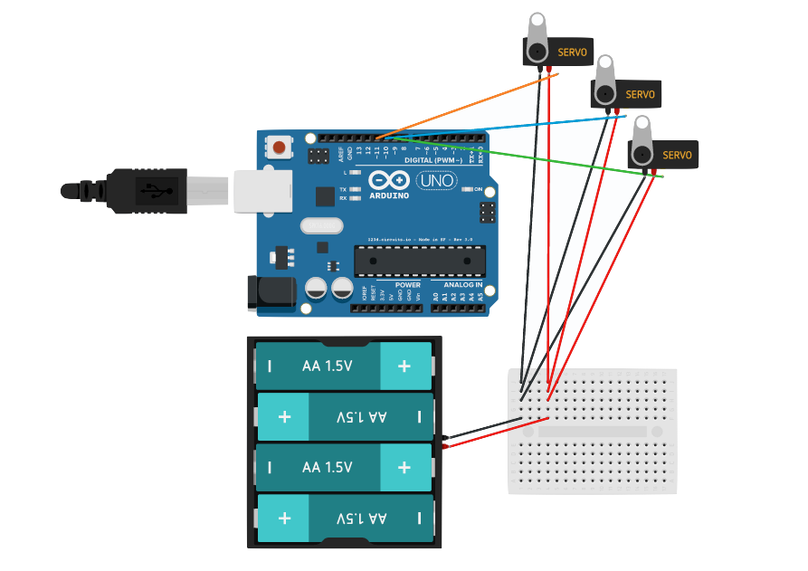
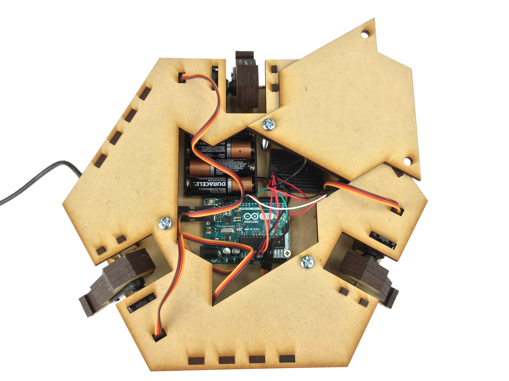
Wire them as shown in the picture.
Miss-wiring could BREAK Arduino and servos RIGHT AWAY, so please be careful.
Yellow wires are for PWM signals, purple wires are for ground and red wires are for DC.
Miss-wiring could BREAK Arduino and servos RIGHT AWAY, so please be careful.
Yellow wires are for PWM signals, purple wires are for ground and red wires are for DC.
Memo: ざっくり分かるArduino 概要編
Memo: ざっくり分かるArduino 拡張編
3-9. Initializing servos [needs update]
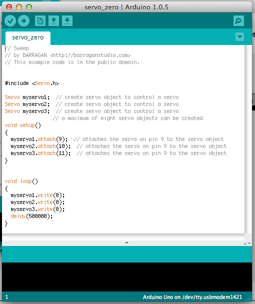
Download this file and unzip it.
OCPC_dlpArduino.zip
Upload servo_zero.ino to your Arduino to initialize the positions of all servos.
(This sketch is not very sophisticated at present.)
After finishing the initialization, upload a empty sketch. (reset.ino)
Upload servo_zero.ino to your Arduino to initialize the positions of all servos.
(This sketch is not very sophisticated at present.)
After finishing the initialization, upload a empty sketch. (reset.ino)
Memo: ざっくり分かるArduino 動作編
5. Assembling the movements
Continue assembling.
5-1. Putting servo horns on the arms
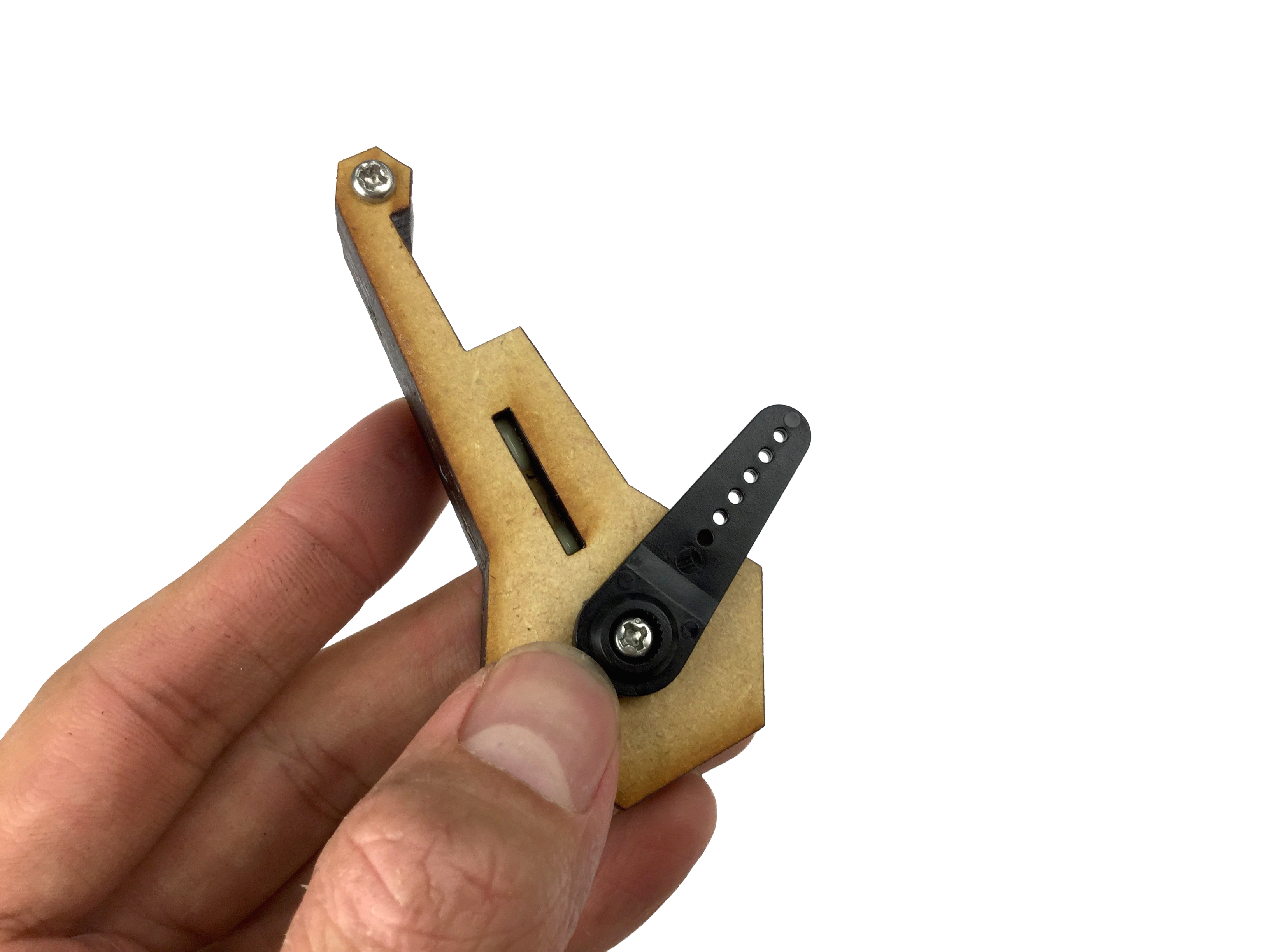
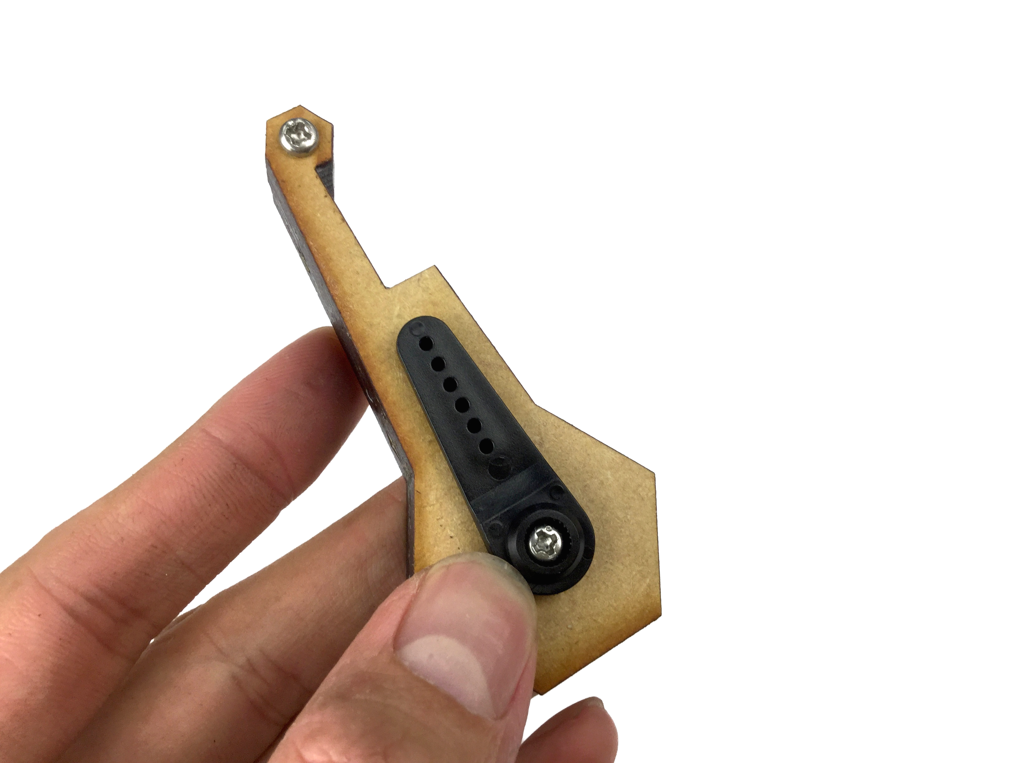
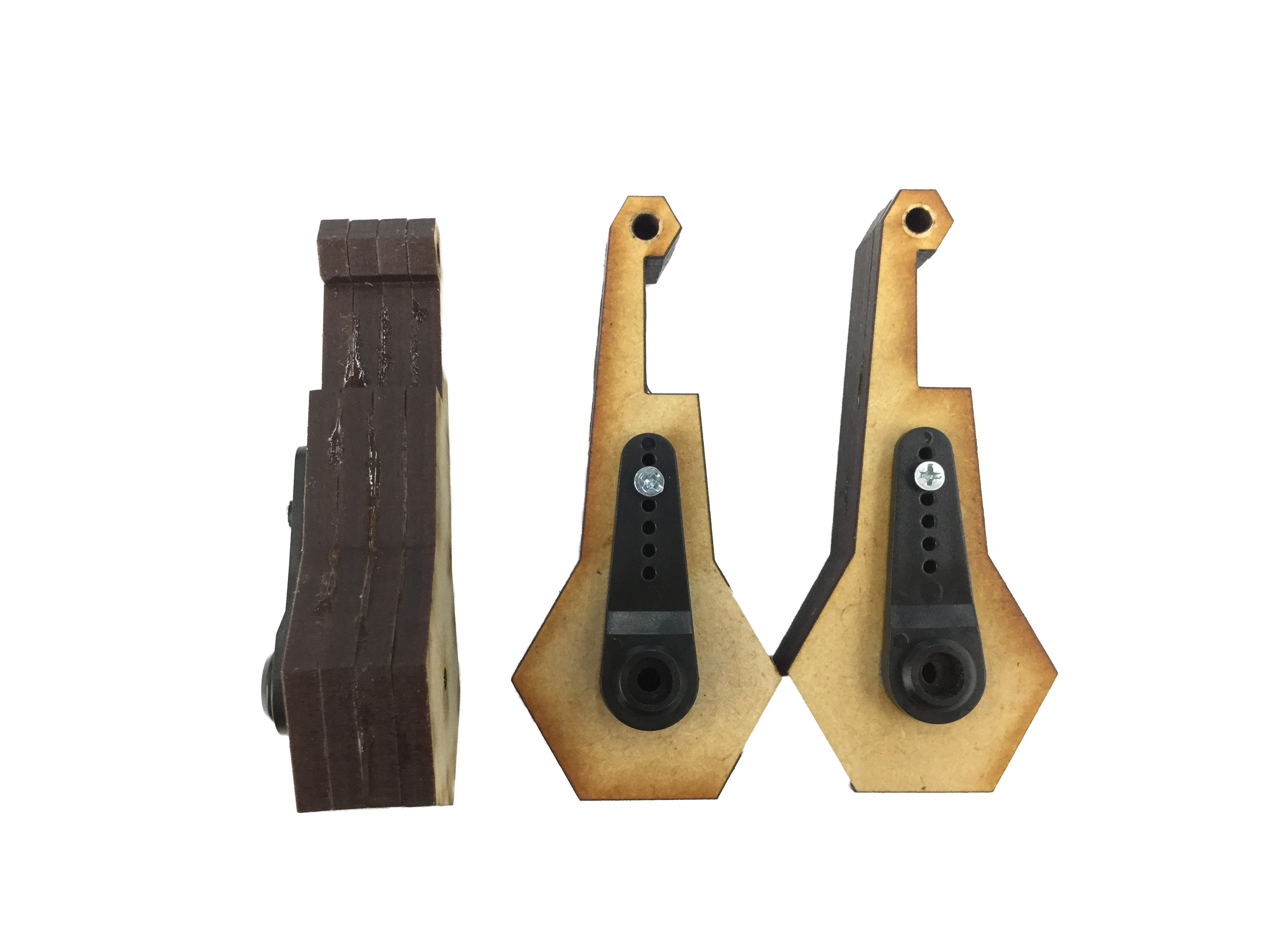
Remove all screws from it first, then pass M2.1 Wood screws (13mm) through a hole on a servo horn and rectangular hole on the arm, BY FORCE.
At that time, also use M3 Pan-head screws (45mm) to keep them in the right position.
Make sure to glue them super-neatly OR YOUR OCPC DOESN'T WORK WELL.
At that time, also use M3 Pan-head screws (45mm) to keep them in the right position.
Make sure to glue them super-neatly OR YOUR OCPC DOESN'T WORK WELL.
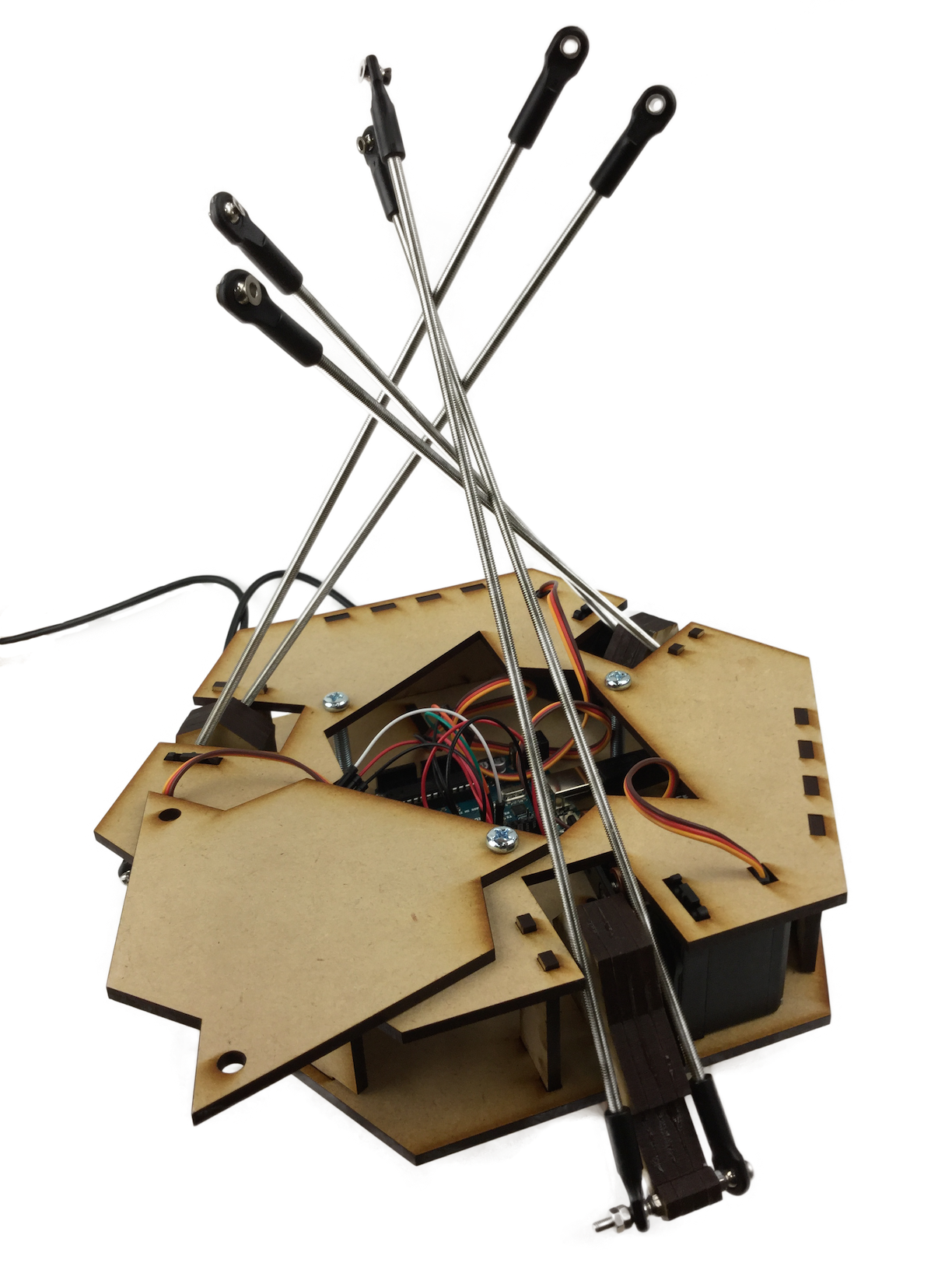
5-2. Assembling the rods
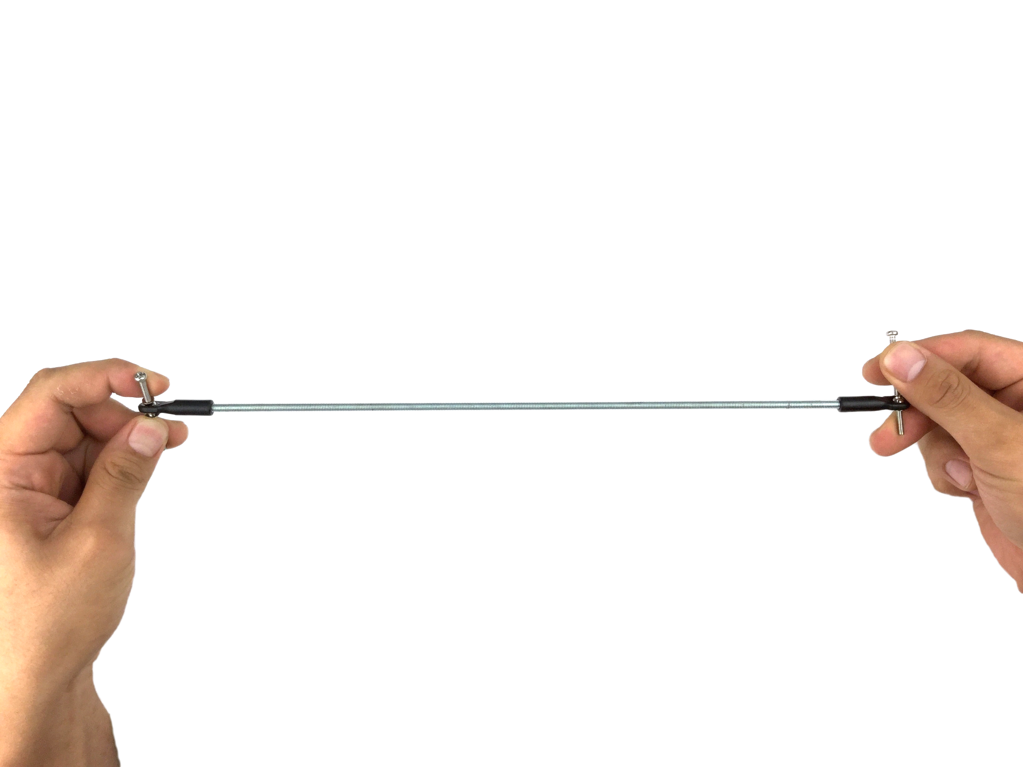
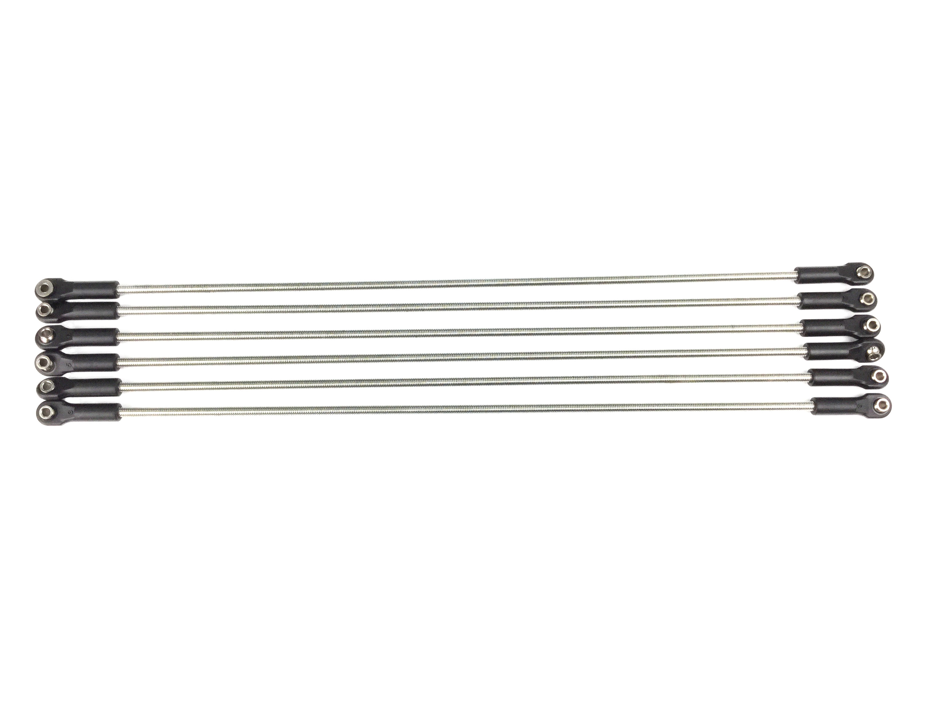
Assemble the rod ends and threaded rods (285mm) to make the rod parts of a parallel link structure.
You can pass through M3 pan-head screws (45mm) to the ends to twist them tightly.
Make sure that all rods are assembled SUPER NEATLY because these rods will work as a parallel link structure.
You can pass through M3 pan-head screws (45mm) to the ends to twist them tightly.
Make sure that all rods are assembled SUPER NEATLY because these rods will work as a parallel link structure.
5-3. Putting the arms and the servos together
Put the arm parts onto servo motors.
Servo horns on the arm parts have gear-like structure that correspond to the gear of the servos.
Put them together to make the lowest angle as it could, and the same angle as the other two.
Servo horns on the arm parts have gear-like structure that correspond to the gear of the servos.
Put them together to make the lowest angle as it could, and the same angle as the other two.
5-4. Pass through the axis

Pass M3 pan-head screws (45mm) through the vertical parts across the servos, arm parts, servo horns and towards the servos.
You need to tighten the screw as it goes into the servo, but DON'T MAKE IT TOO TIGHT OR SERVO GETS BROKEN RIGHT AWAY.
Your screw may be too long for that, but just don't worry.
You need to tighten the screw as it goes into the servo, but DON'T MAKE IT TOO TIGHT OR SERVO GETS BROKEN RIGHT AWAY.
Your screw may be too long for that, but just don't worry.
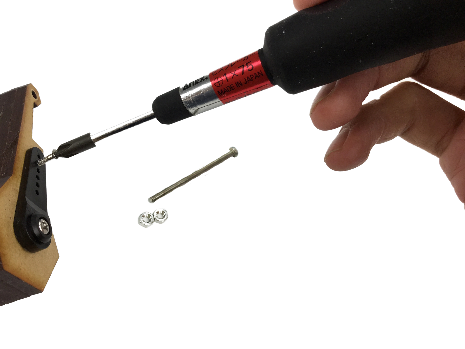
5-5. Put the joints on the top plate
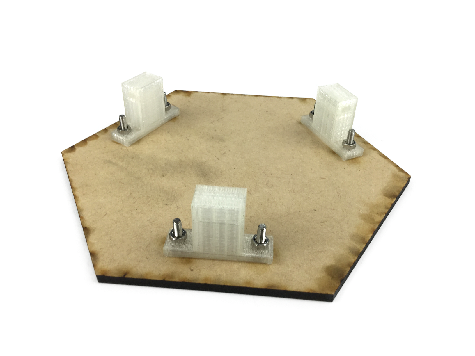
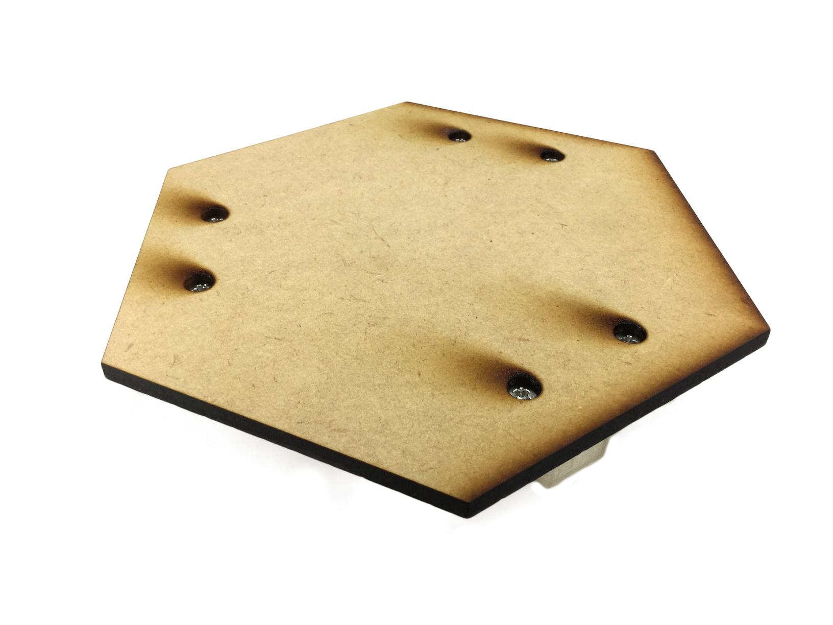
Pick 3d-printed joint parts and fix them on the top plate by using M3 flat-head screws (15mm) and M3 nuts as shown in the picture.
Notice that the heads of the screws doesn't go nay higher than the surface of the plate.
Notice that the heads of the screws doesn't go nay higher than the surface of the plate.
5-6. Putting the rods on 1/2
Use M3 pan-head screws (45mm) and M3 nuts to put the rods of step 5-2 on the arms of servos.
As shown in the picture on the right, you will need 4 nuts for each screw.
As shown in the picture on the right, you will need 4 nuts for each screw.
Memo : ダブルナット
5-7. Putting the rods on 2/2
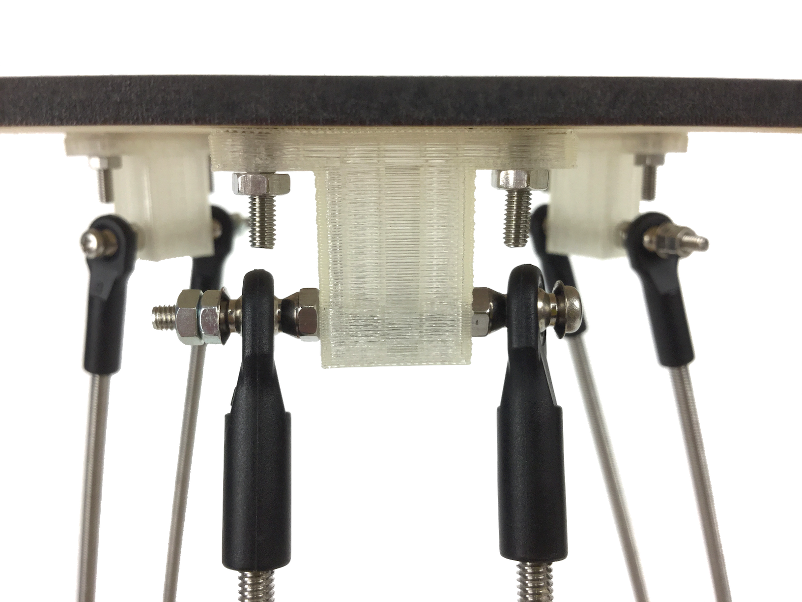
Just like you've done in the last step, use M3 pan-head screws (45mm) and M3 nuts to put the rods of step 5-2 on the joint parts on the top plate.
As shown in the picture on the right, as before, you will need 4 nuts for each screws.
As shown in the picture on the right, as before, you will need 4 nuts for each screws.
6. Complete!
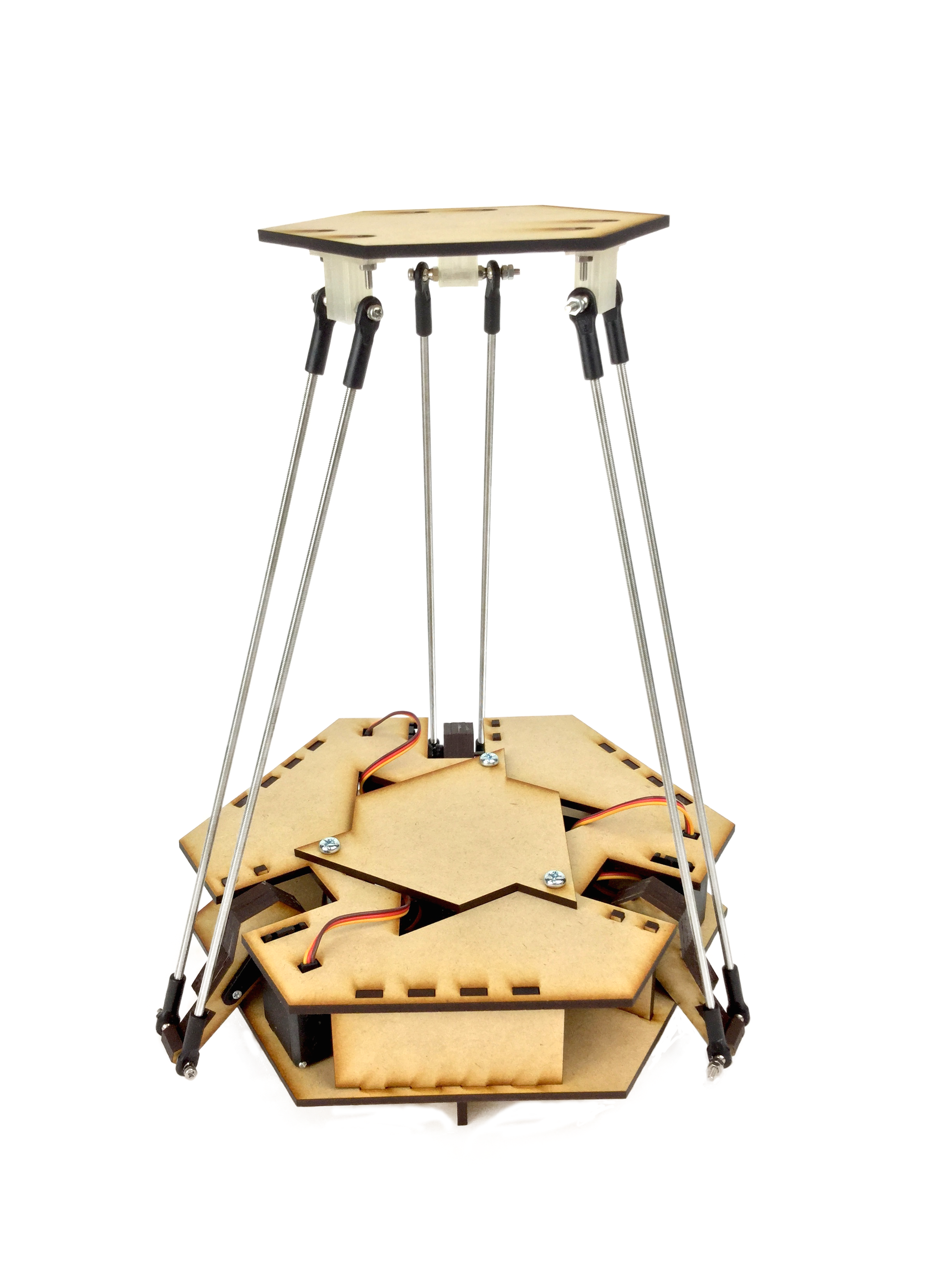
Congratulations!
[注意] 本当に完成してる?
見た目にできあがっていても、
つっかえながら動いていたり、
サーボモーターの動きが筐体にぶつかっていたりなど、
少し動きが悪いことがあります。
そういった場合には、決してそのまま放置しないでください。
そうした現象には必ず原因があります。
(そして、想定されるトラブルの多くは、
該当する各工程や、すぐ下の7-1に注意書きとして書いてあります。)
トラブルを抱えた状態のまま動かし続けると、
サーボモーターやArduinoを壊してしまうことも少なくありません。
きちんと原因を究明しましょう。
7. 動作確認 [以下要改訂]
動かしてみましょう。
7-1. 上下に動かしてみる
deltaTest_dlp.zipからdeltaTest_dlp.inoを開き、
腕/サーボホーンを外して、4-7をやり直してください。
5-3, 5-4の注意点を守っているか確認してください。
Arduinoに書き込んで動かしてみましょう。
まっすぐ上下に動けば成功です。
deltaTest_homeAll.inoを書き込むと、
サーボに負荷をかけずに元の位置に戻せます。
- サーボの動きはじめ/終わりのタイミングが違う
腕/サーボホーンを外して、4-7をやり直してください。
- 斜めに動いている/天板が傾いている
5-3, 5-4の注意点を守っているか確認してください。
- 動きながら天板がガタガタする
きつく締め直してください。
7-2. 3つのサーボを独立に動かしてみる
このプログラムをArduinoIDEから直接書き込んで、
deltaTest2_dlp
3つのサーボが等価に動くかどうかを確認しましょう。
また、台座の動く最大範囲を把握しましょう。
3つのサーボモーターを同時ではなく「それぞれ独立に」動かしてみます。
deltaTest2_dlp
3つのサーボが等価に動くかどうかを確認しましょう。
また、台座の動く最大範囲を把握しましょう。
7-3. ArduinoとProcessingを通信し、マウスで動かしてみる 1
ArduinoのソースコードとProcessingのソースコードが入っています。
Control P5 Libraryの入ったProcessing2.2.1と、Arduinoが必要です。
Arduino側にソフトウェアを書きこんだあと、
Control P5 Libraryの入ったProcessing2.2.1と、Arduinoが必要です。
(通常はProcessingのソフト内からインストールできます。)
Arduino側にソフトウェアを書きこんだあと、
PC上でProcessingを実行してマウスで操作します。
Memo: Processingについて
7-4. ArduinoとProcessingを通信し、マウスで動かしてみる 2
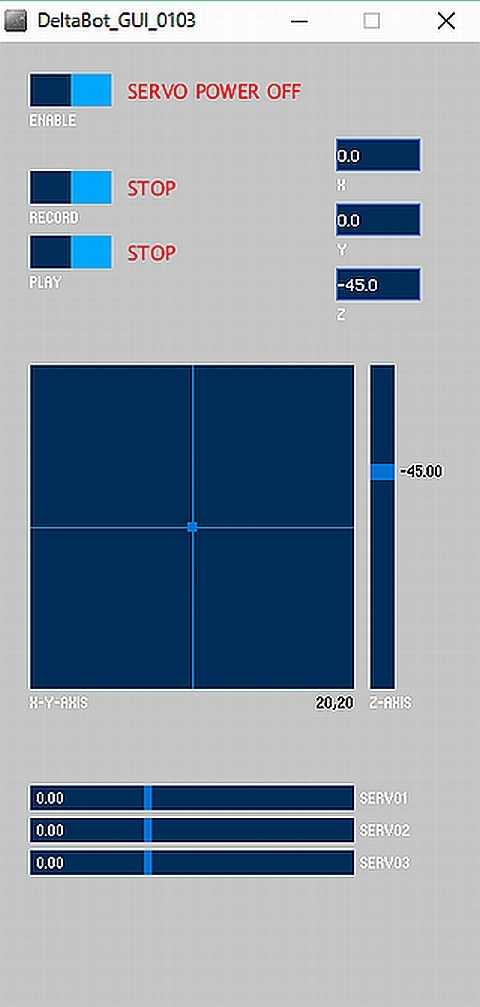
Processingを実行すると右のような画面が立ち上がります。
最初は"SERVO POWER OFF"になってしますので、
最初は"SERVO POWER OFF"になってしますので、
[ENABLE]ボタンを押してPOWER ONにします。
ここでサーボモータが反応するはずです。
※作動しない場合は、
※作動しない場合は、
myPort = new Serial(this, Serial.list()[X], 9600)
という行の[X]部分の数字を
0,1,2...と順番に変えてみてください。
[RECORD]ボタンを押すと
[RECORD]ボタンを押すと
動作を記録するモードに入ります。(制限時間あり)
[PLAY]ボタンを押すと記録された動作を反復再生します。
また、[RECORD]は何度でもやり直すことができます。
[PLAY]ボタンを押すと記録された動作を反復再生します。
また、[RECORD]は何度でもやり直すことができます。
7-5. 録画再生をつかわず自分でプログラミングをする
Processingの知識が多少あれば、自分でOCPCを動かすことができます。
void draw(){}の中で
void draw(){}の中で
xp=15; yp=15; zp=-40;
と指定すると座標が設定され、
setThetasfromXYZ();
を実行すると機械にその座標値が送信、
updateGuiElements();
setThetasfromXYZ();
を実行すると機械にその座標値が送信、
updateGuiElements();
を実行すると座標値が画面上に反映されます。
xyzが機械の範囲外になると動かず反映もされないので、
xyzが機械の範囲外になると動かず反映もされないので、
まずはマウスで可動範囲を調べてください。
(なおzは±が逆になっています)