必要な部品を揃えよう/Prepare parts
以下の商品をご購入ください
Prepare those three products below:
・ポータブルFM音源キーボード製作キット(全部入り)
(Portable FM Tone Generator Assembly Kit)
ポータブルFM音源キーボード製作キット(Portable FM Tone Generator Assembly Kit)
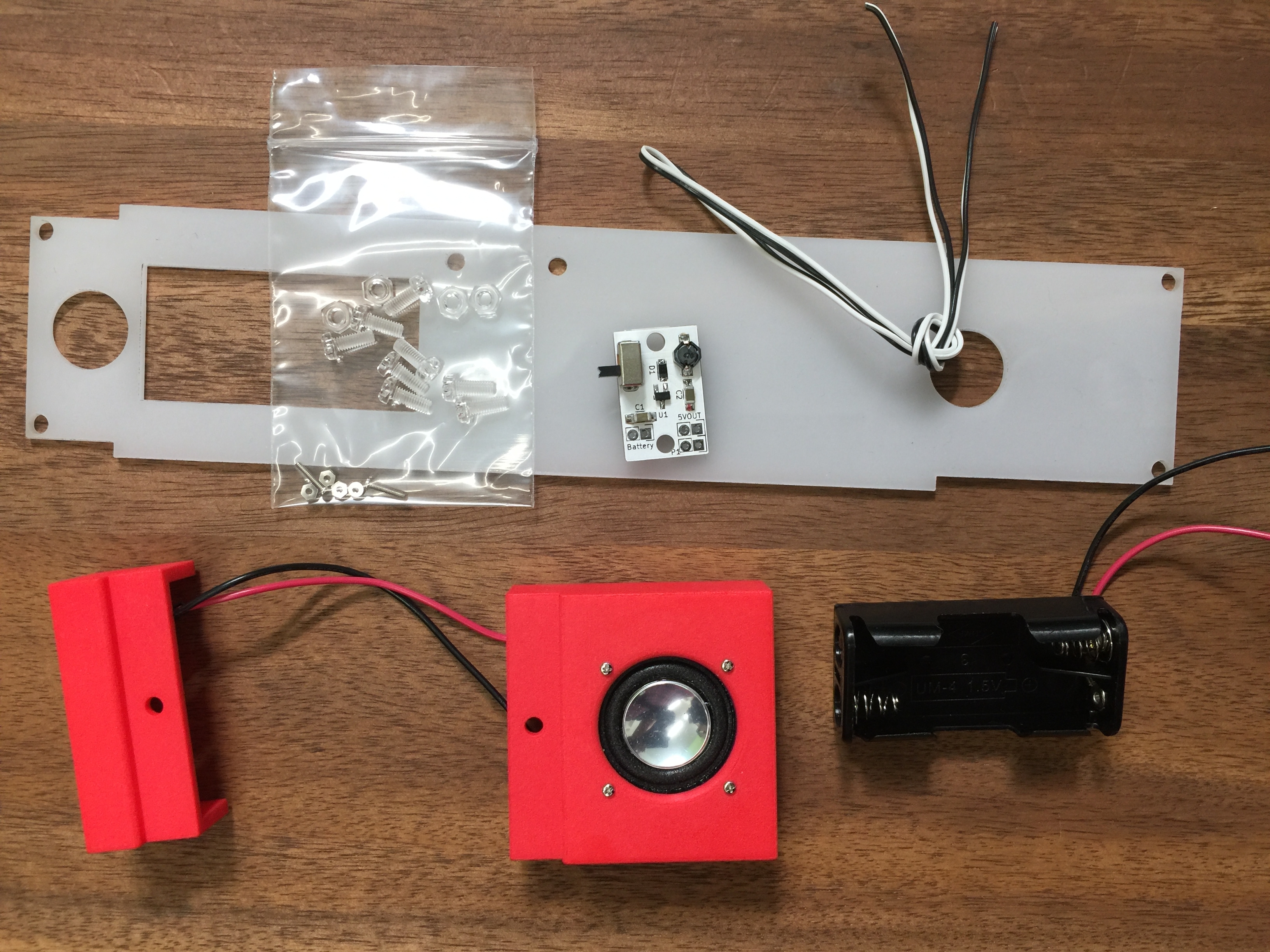
製作に必要な部品を全部入りキットとして販売しております。本キットは奇楽堂のネットショップにて扱います。
全部入りキットには写真の部品他、TouchMIDI25key、YMF825Boardが入っています。
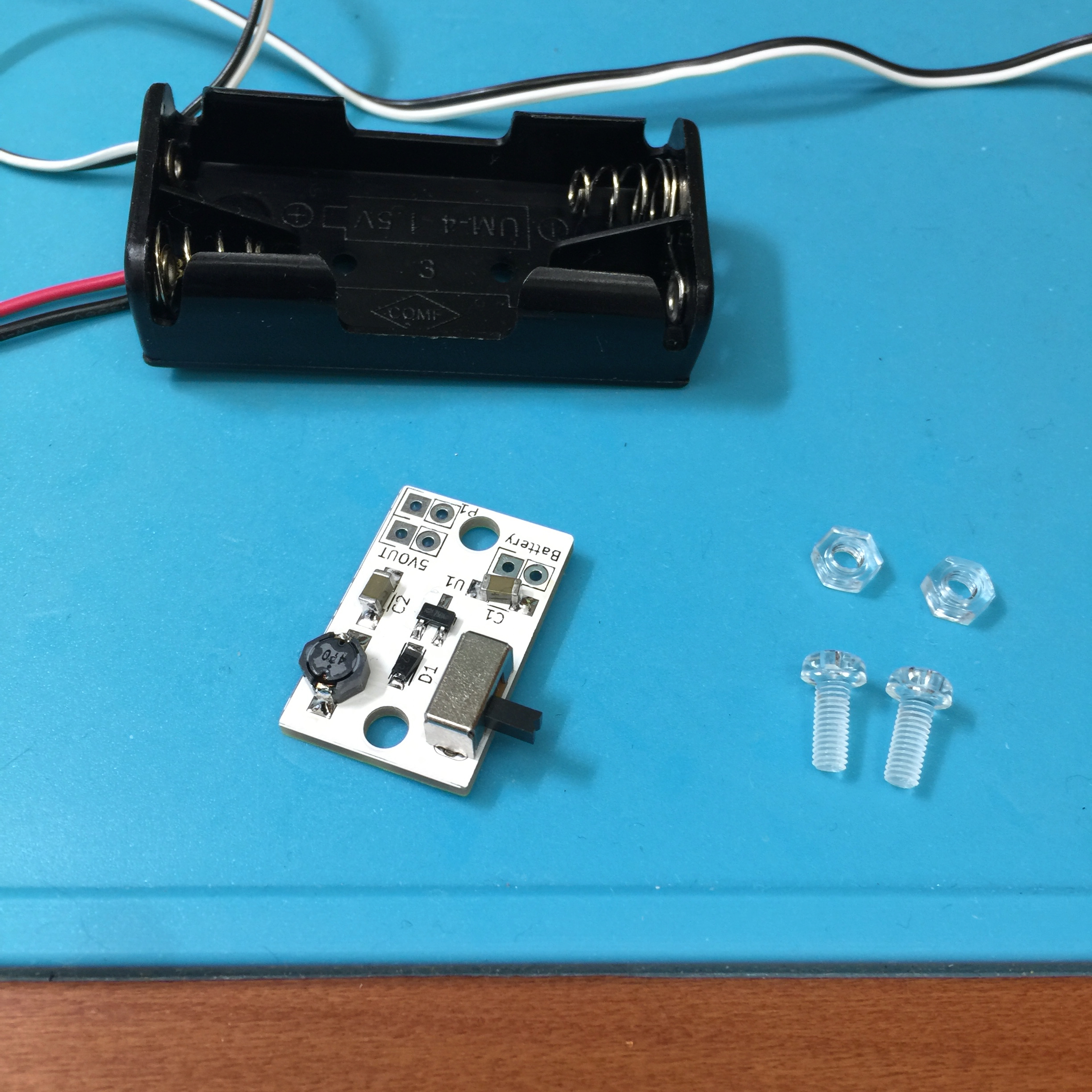
製作キット内容物(Parts list of the kit)
・スピーカー(speaker)
・3Dプリントによる左右の台座(left/right support by 3D printing)
・乳白色のアクリル板による底板(acrylic bottom plate)
・昇圧回路モジュール(voltage converter module: VCM)
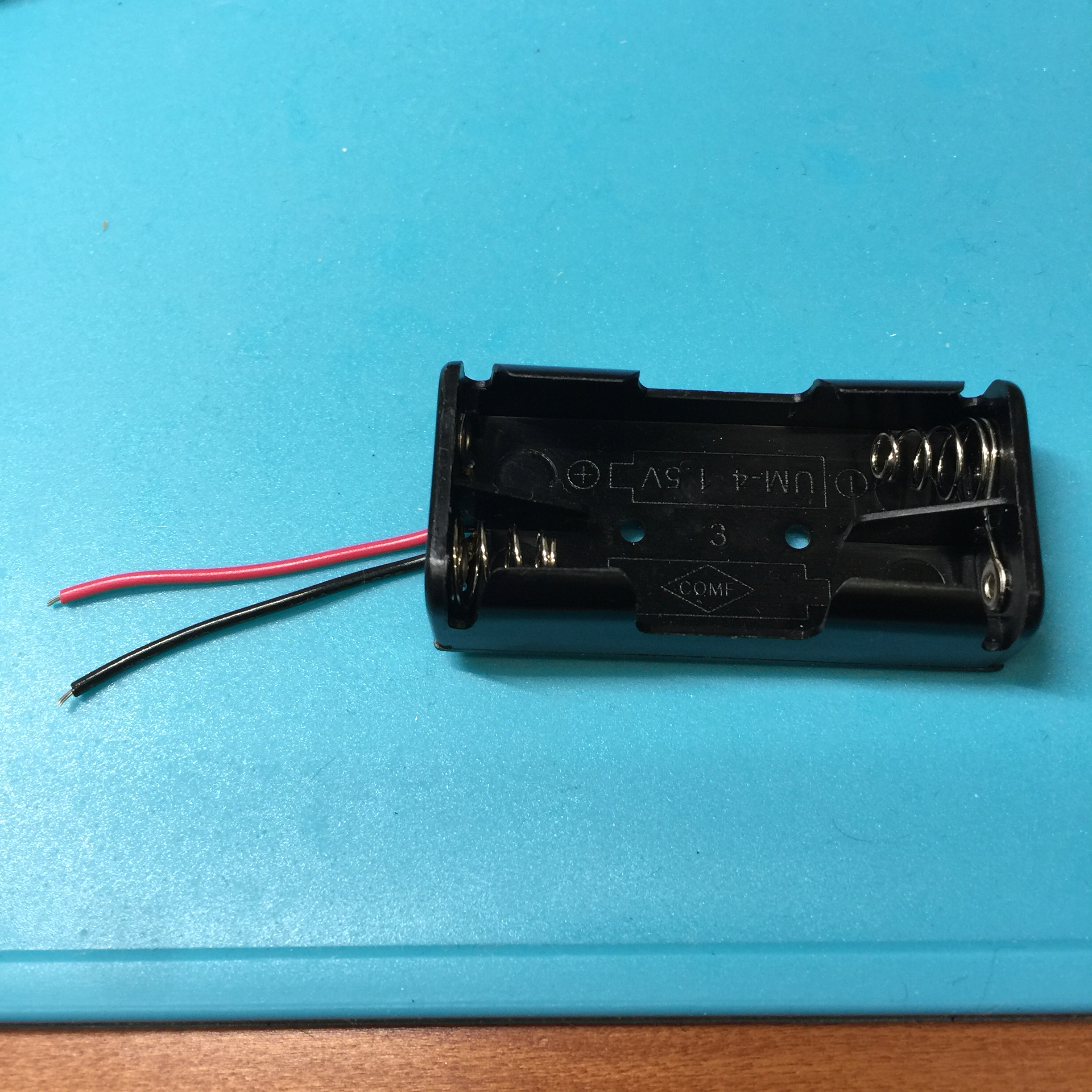
・単4電池ボックス(battery box)
・ネジ類(screws)
スピーカー取り付け用小型ネジ&ナット:4セット
四角ナット:4つ
透明ネジ:8つ
透明ナット:4つ
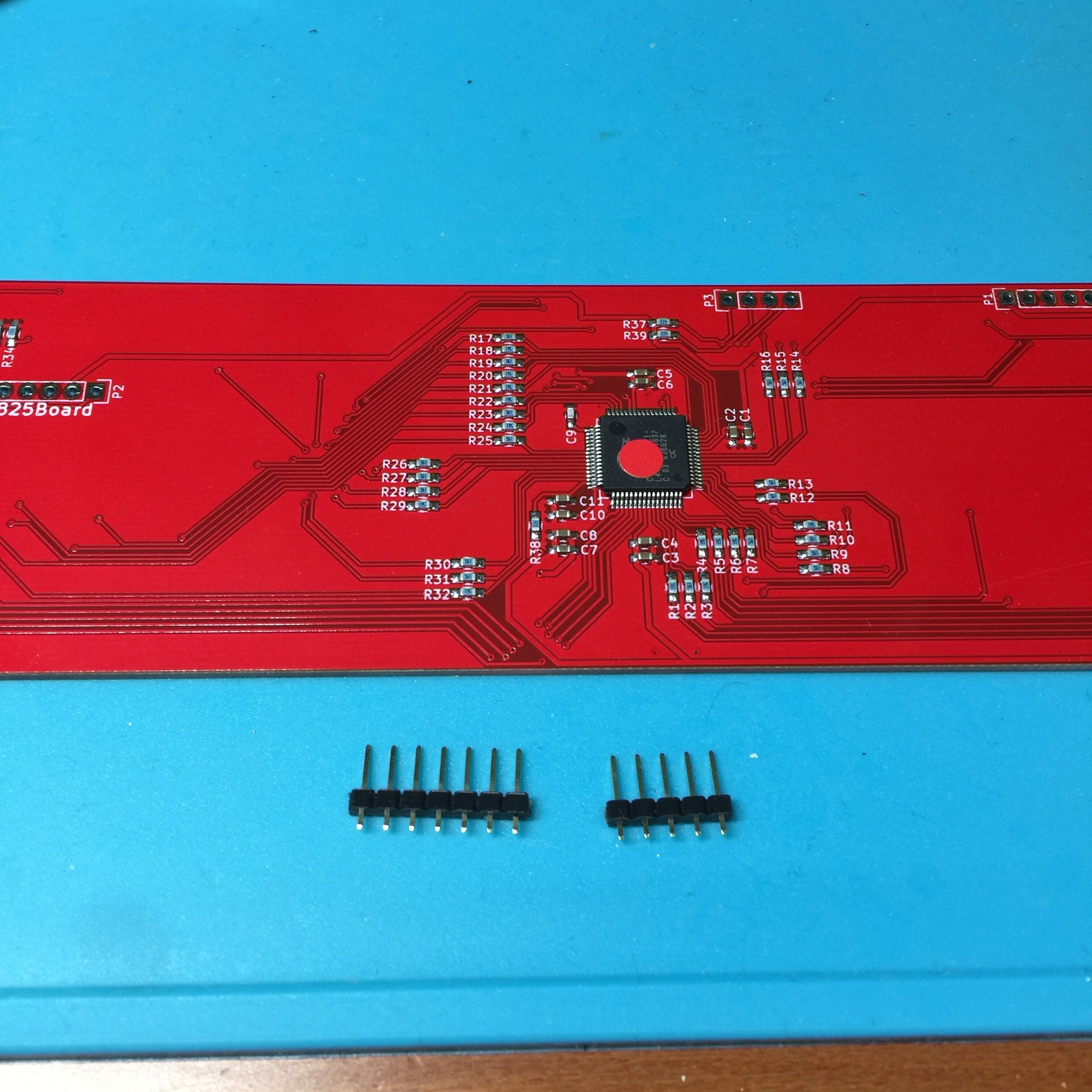
・ピンヘッダ(pin header)
・ケーブル(cable)
・両面テープ(double-sided tape)
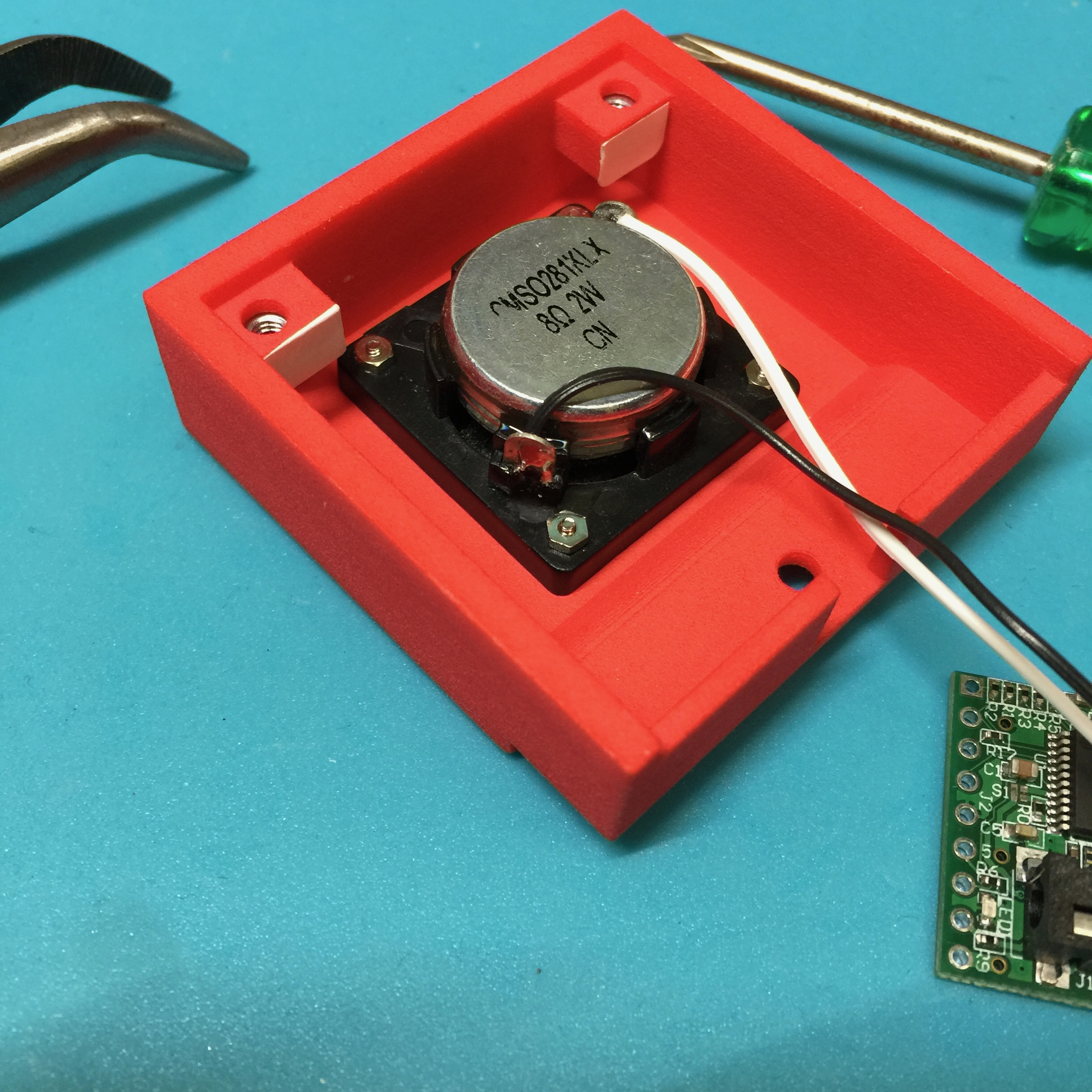
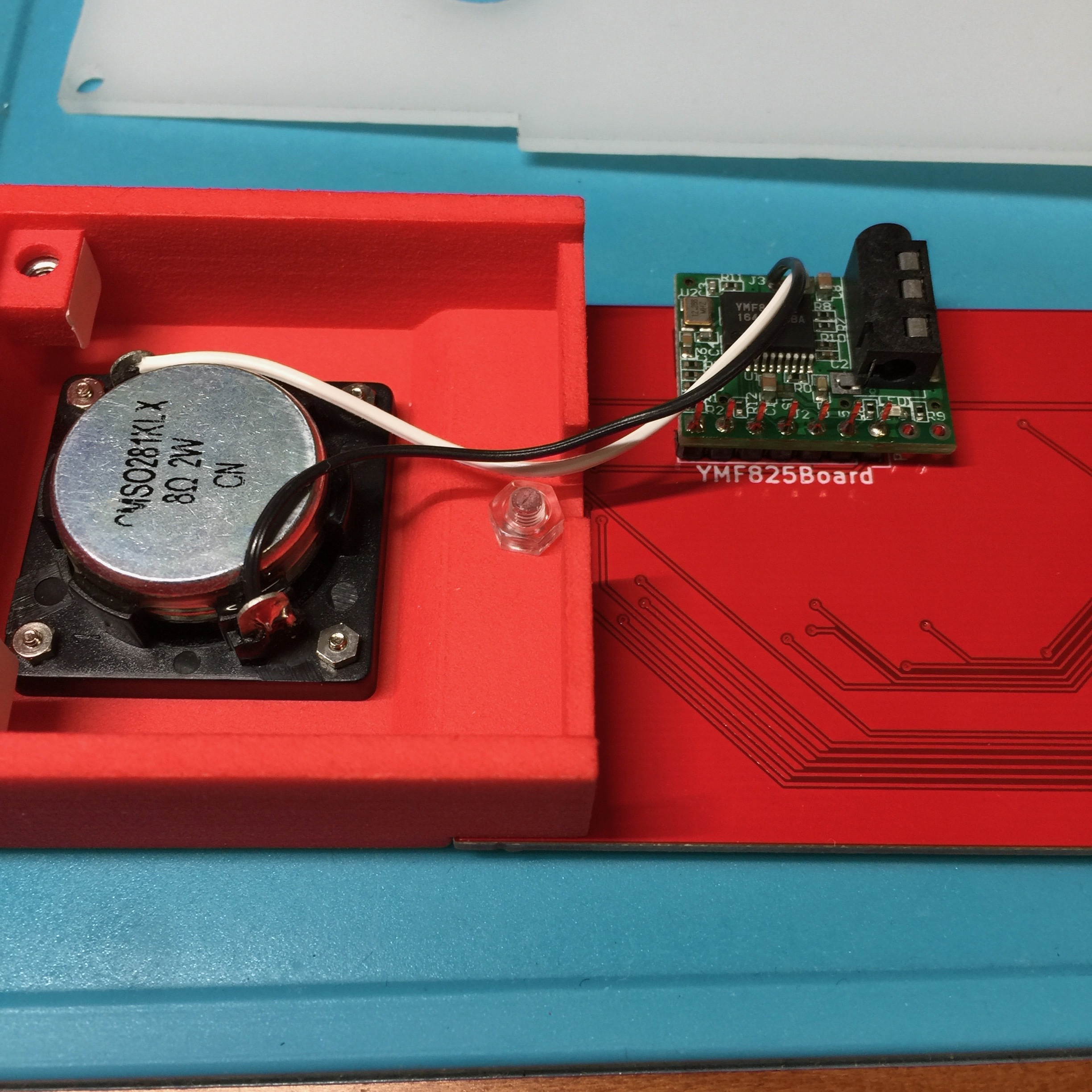
スピーカーを取り付けよう/Assemble a speaker
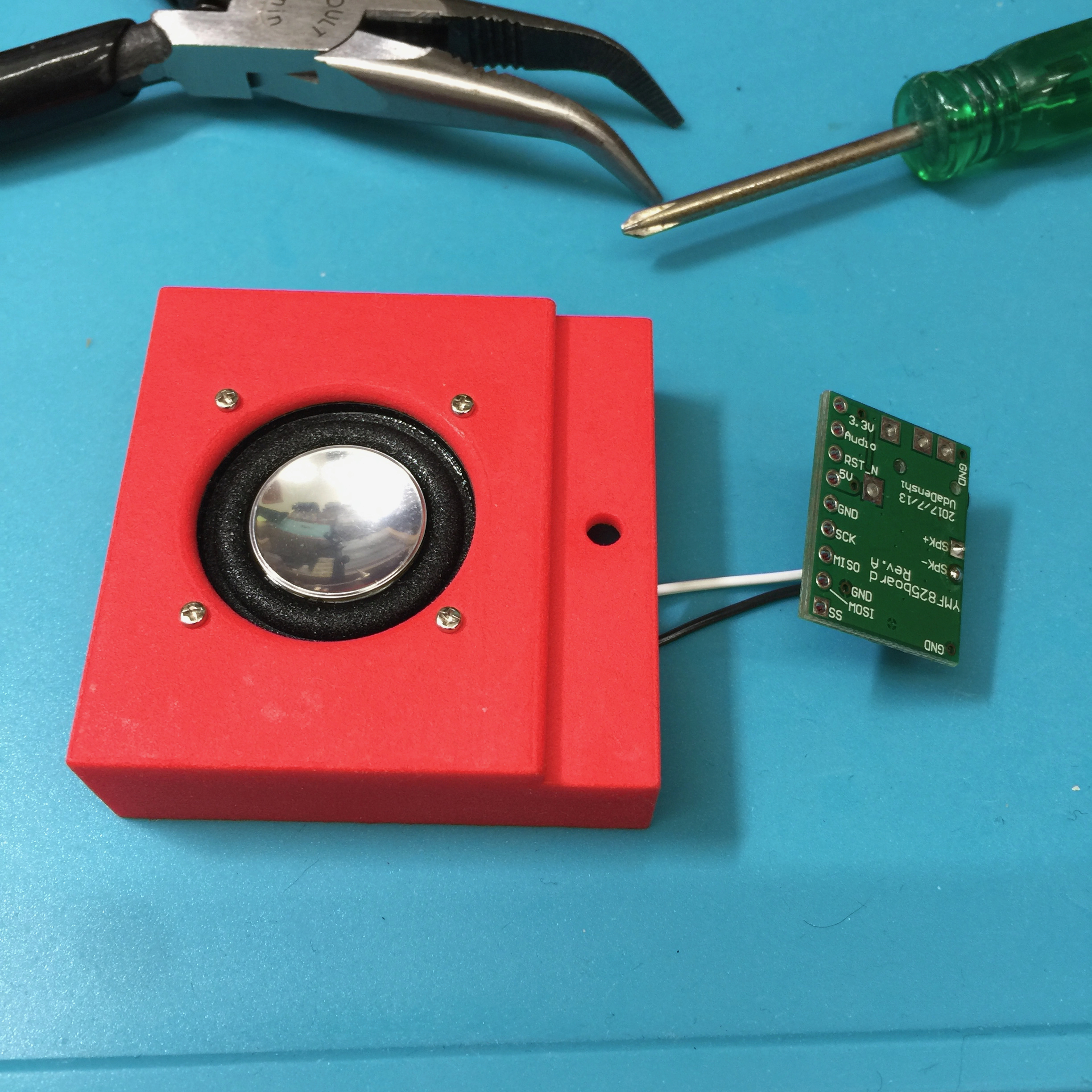
スピーカーとYMF825Boardをハンダ付けでケーブル接続します。そのあと、3Dプリントの台座にスピーカーを取り付けます。
Solder the speaker and YMF825Board for cable connection. After that, attach the speaker to the 3D printed right support.
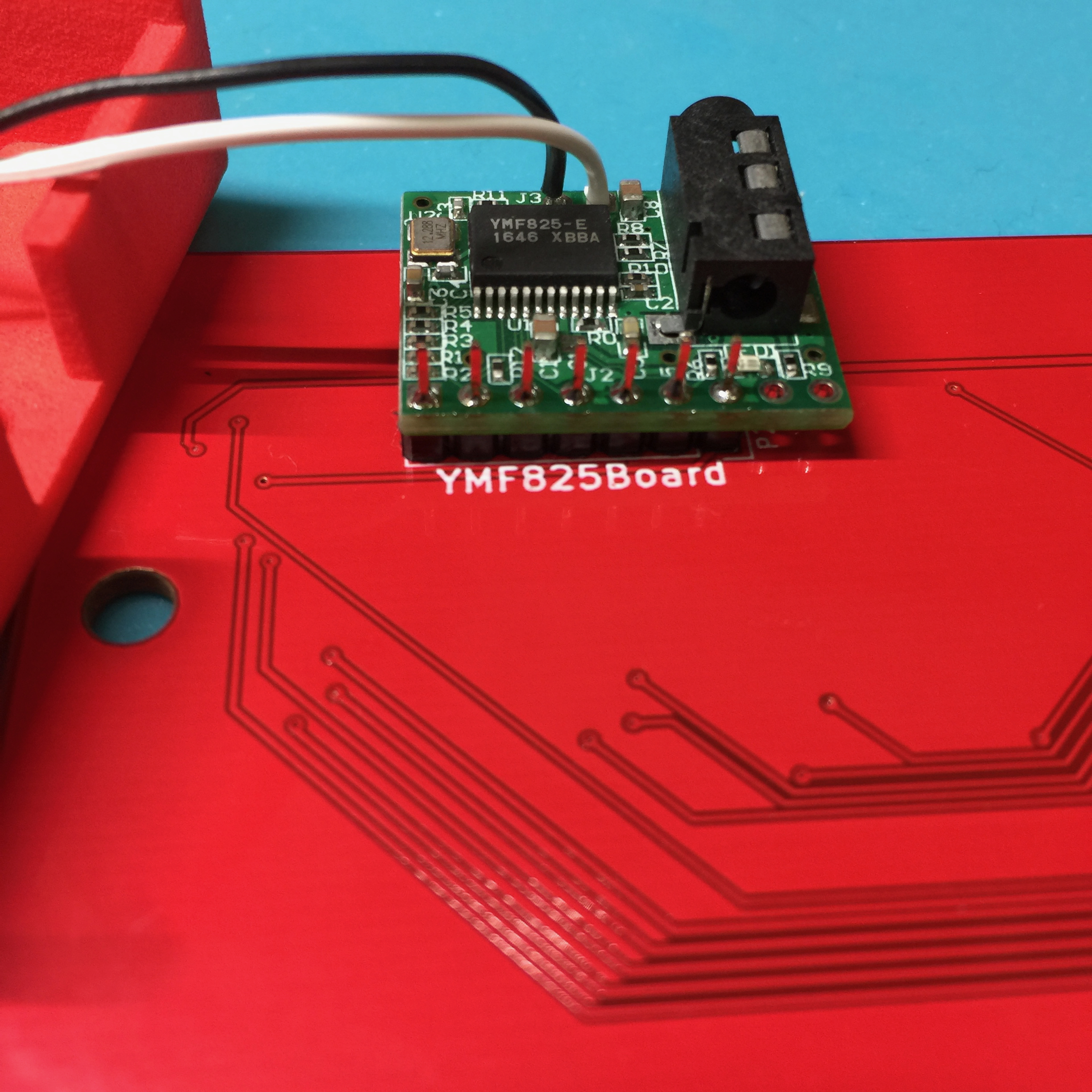
YMF825Boardとスピーカを接続
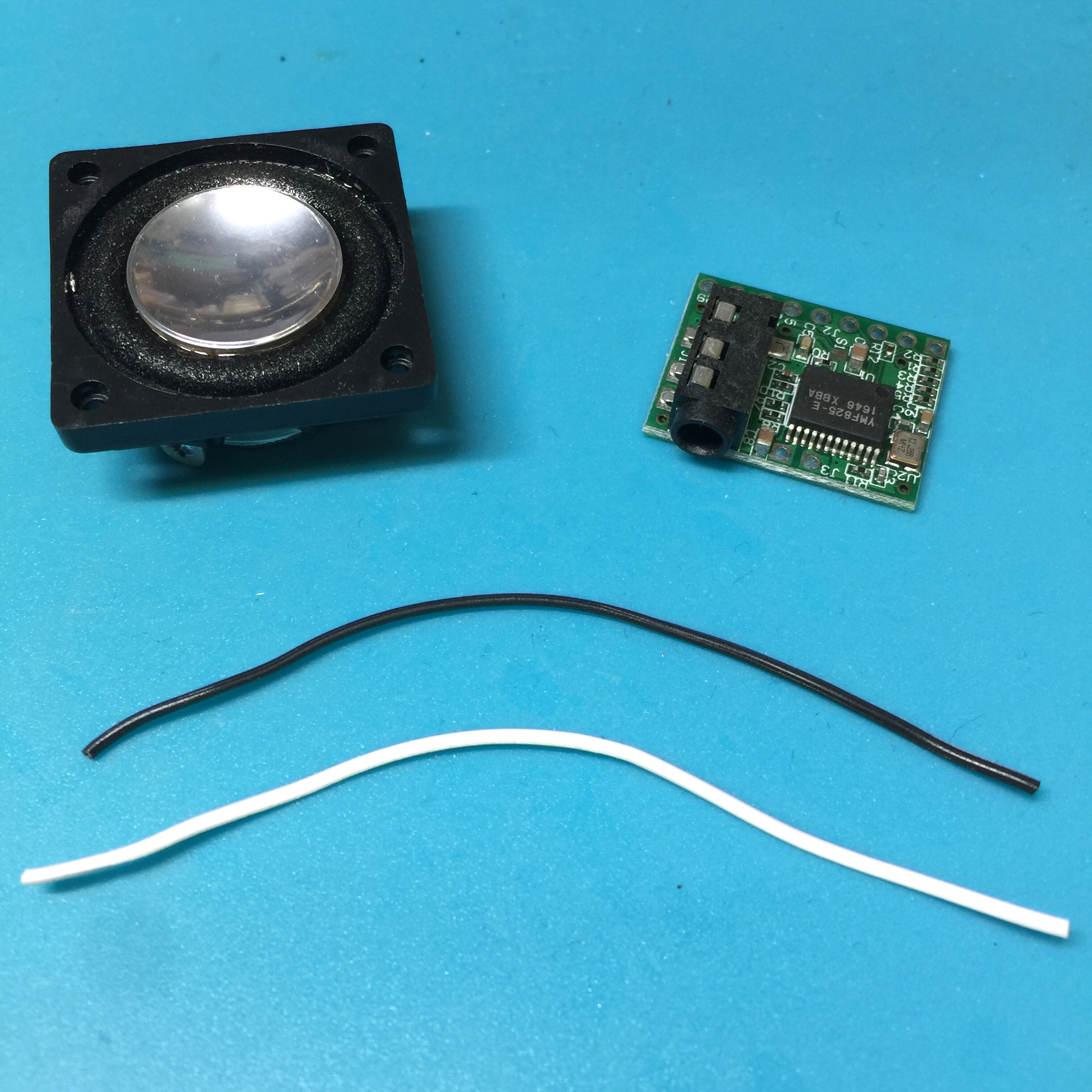
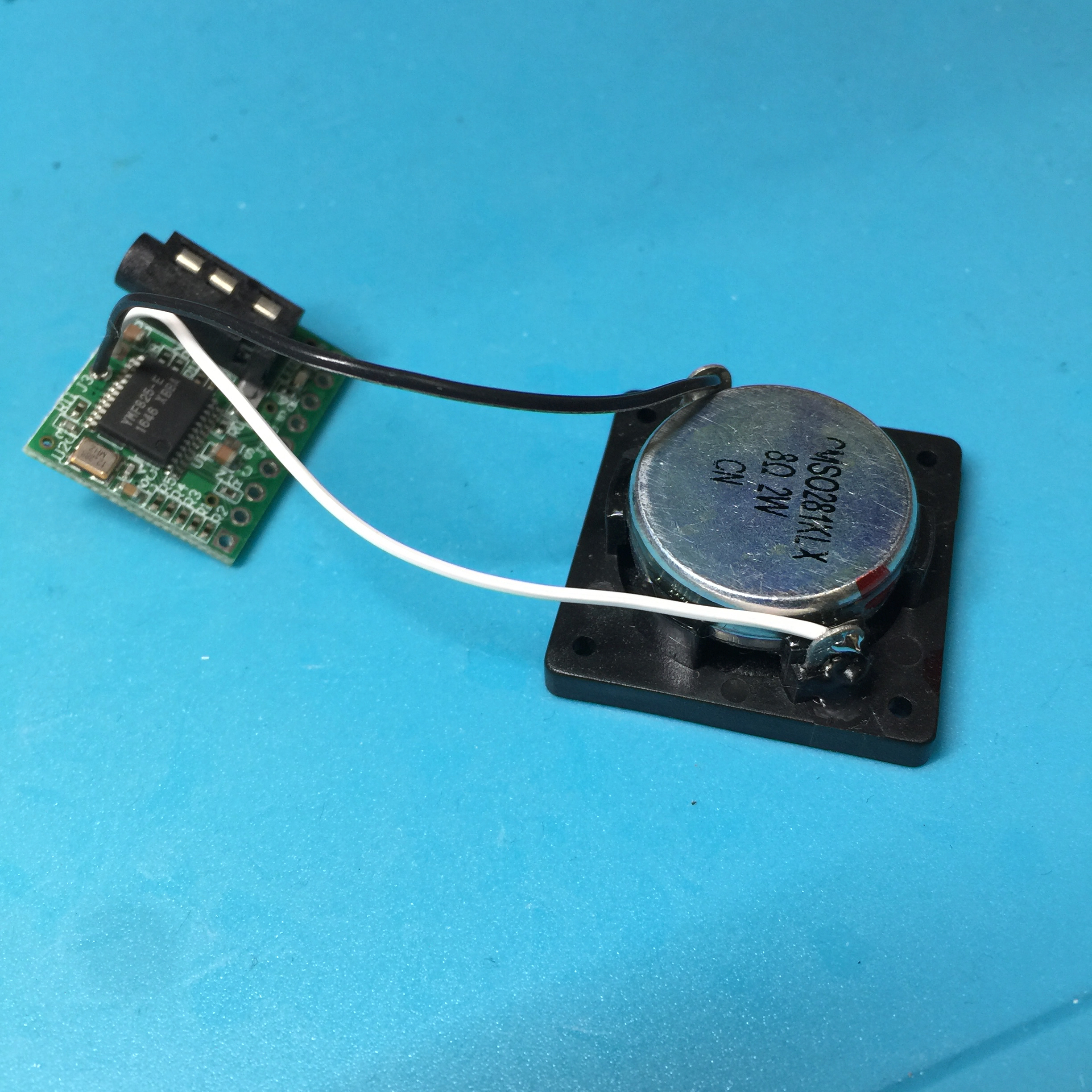
まずケーブルを8cm程度に切ります。このケーブルをYMF825Boardのスピーカー用端子にハンダ付けします。
ケーブルのもう片側をスピーカーにハンダ付けします。
Cut the cable to about 8cm. Solder this cable to the speaker terminal of YMF825Board. Solder the other side of cable to the speaker.
3Dプリントの台座に四角ナットを挿入
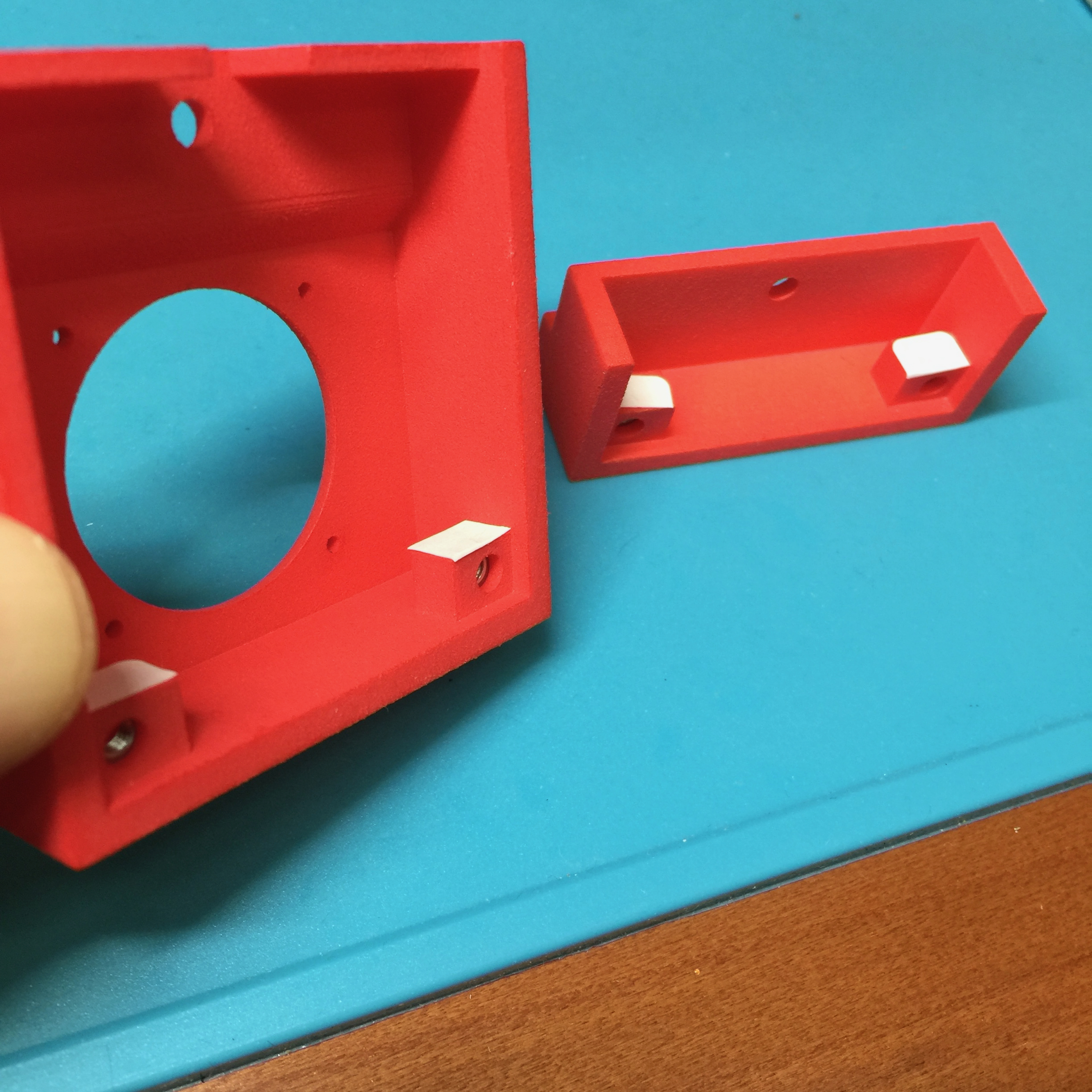
3Dプリントの台座の下側に四角ナットを入れる細い穴があるので、そこに四角ナットを挿入します。四角ナットが落ちてこないように、穴をテープなどで塞ぎます。
There is a narrow hole to put a square nut under the supports by 3D print, so insert a square nut there. Close the hole with tape etc. so that the square nut does not fall off.
スピーカーをネジ止めする
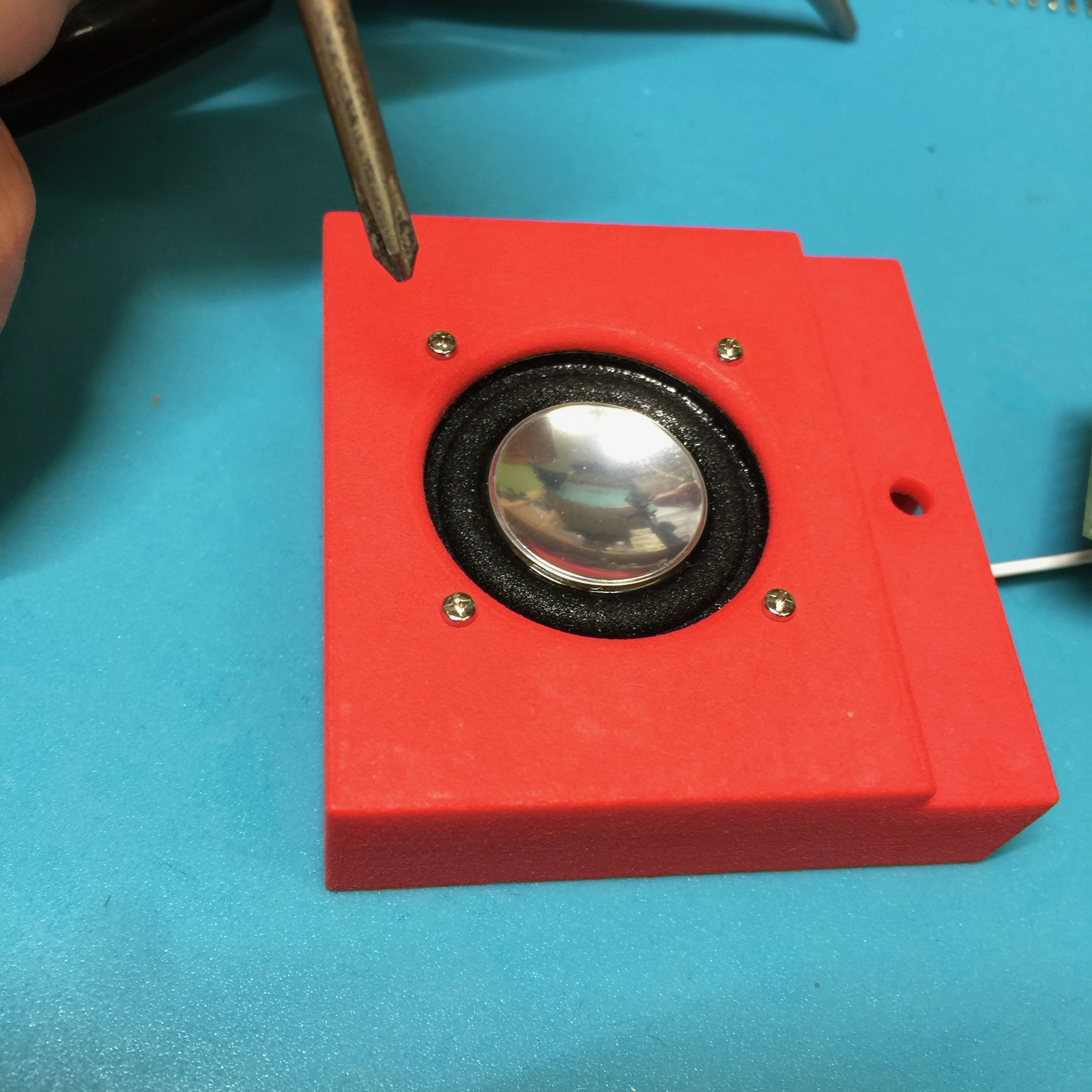
スピーカー用台座とスピーカーを小型のネジで4箇所止めます。
ネジはかなり小さく、スピーカーの磁石にくっついたりしてちょっと難儀しますが、ラジオペンチでナットをうまく固定して、ネジ止めしてみてください。
Secure the support for speaker and speaker at 4 positions with small screws.
The screws are quite small. Please fix the nut properly with a radio pliers and try to screw it.
昇圧回路モジュールを取り付けよう/Assemble power unit
電池ボックス、昇圧回路モジュールを配線して、底板に取り付けます。
Wire the battery box and the VCM and attach them to the bottom plate.
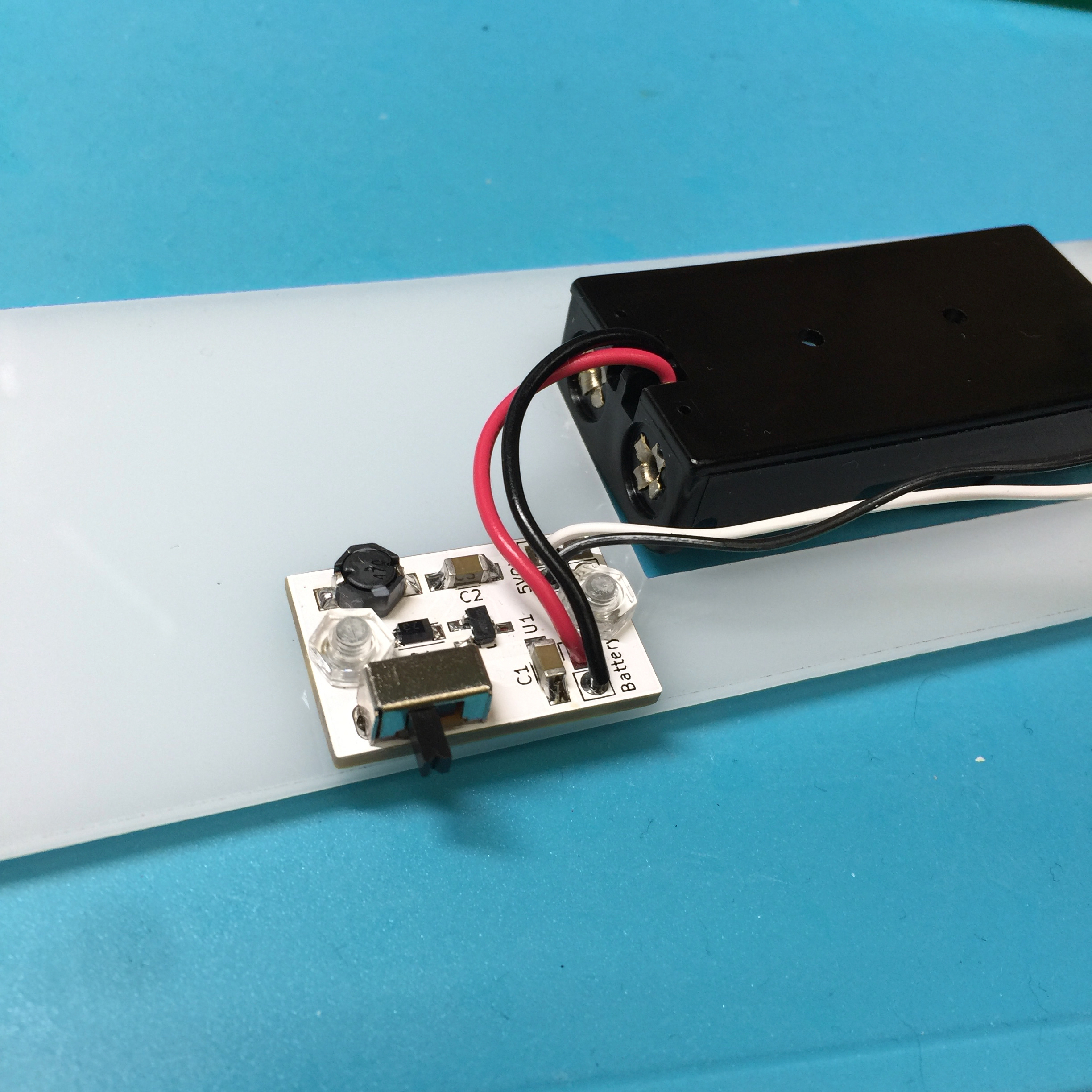
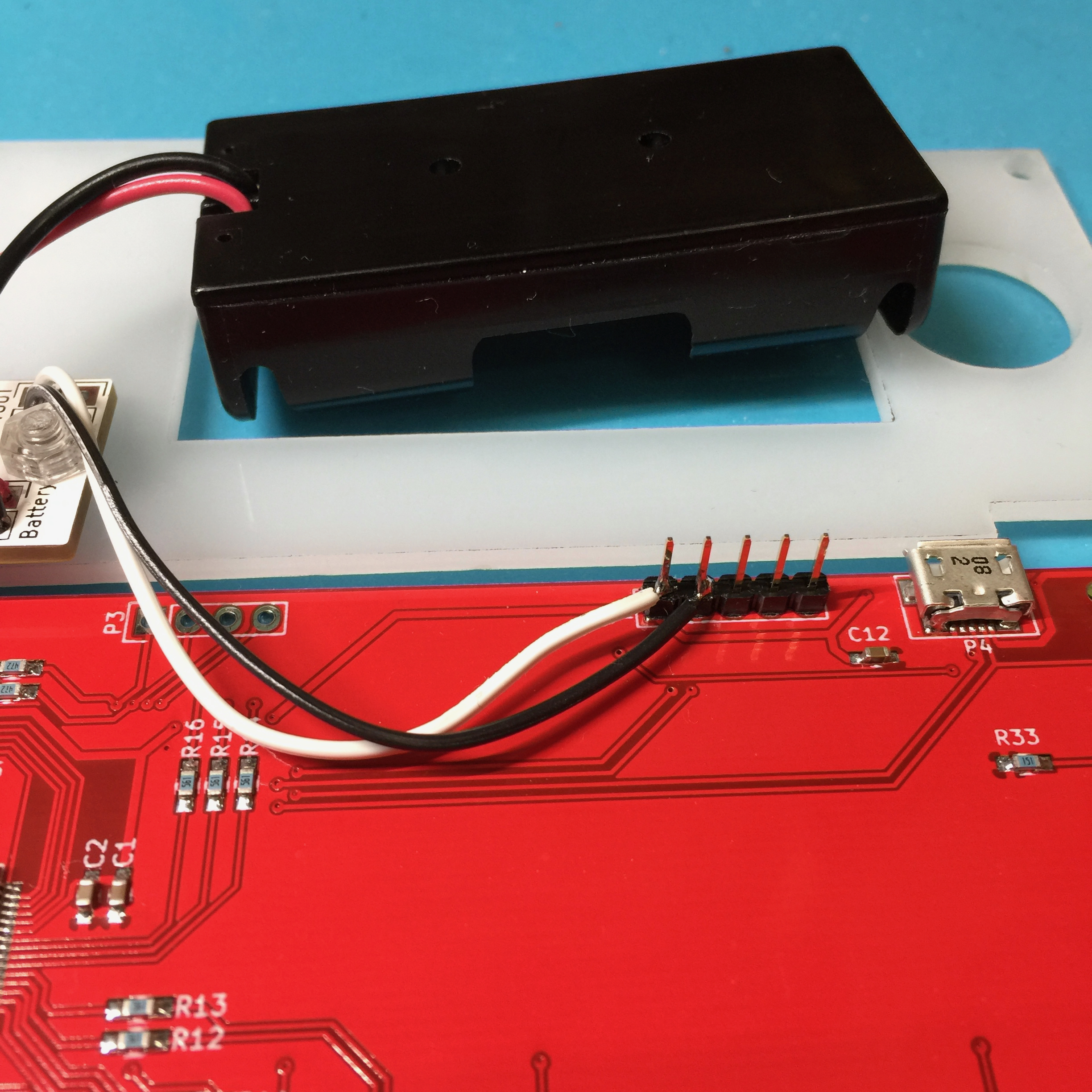
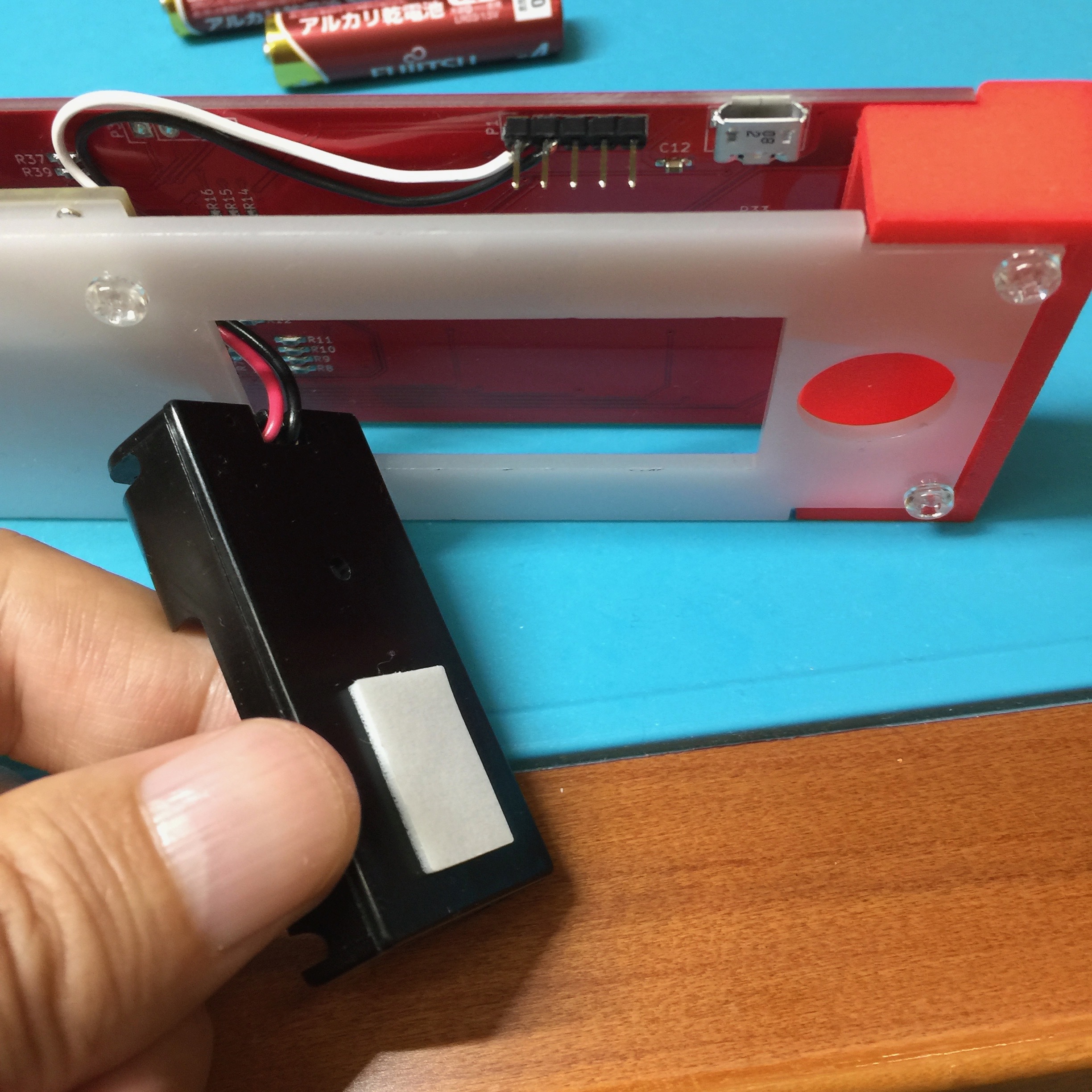
電池ボックスと昇圧回路をケーブル接続
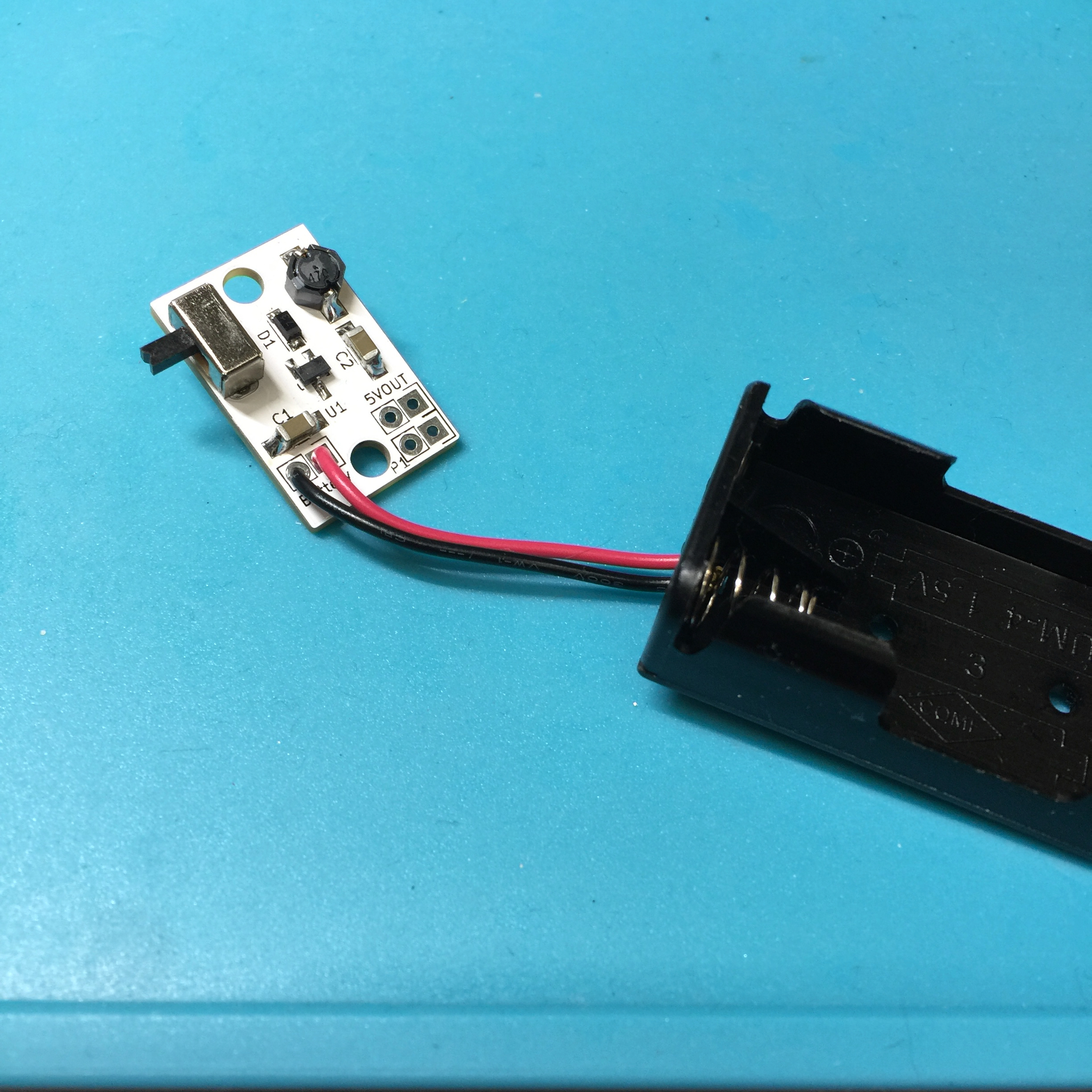
まず電池ボックスのケーブルを長さ4cmほどで切断します。
このケーブルを昇圧回路モジュールのBattery端子にハンダ付けします。四角い穴が+側、丸い穴がー側(GND)です。
Cut the cable of the battery box at a length of about 4cm.
Solder this cable to the Battery terminal of the VCM. The square hole is the + side, the round hole is the - side (GND).
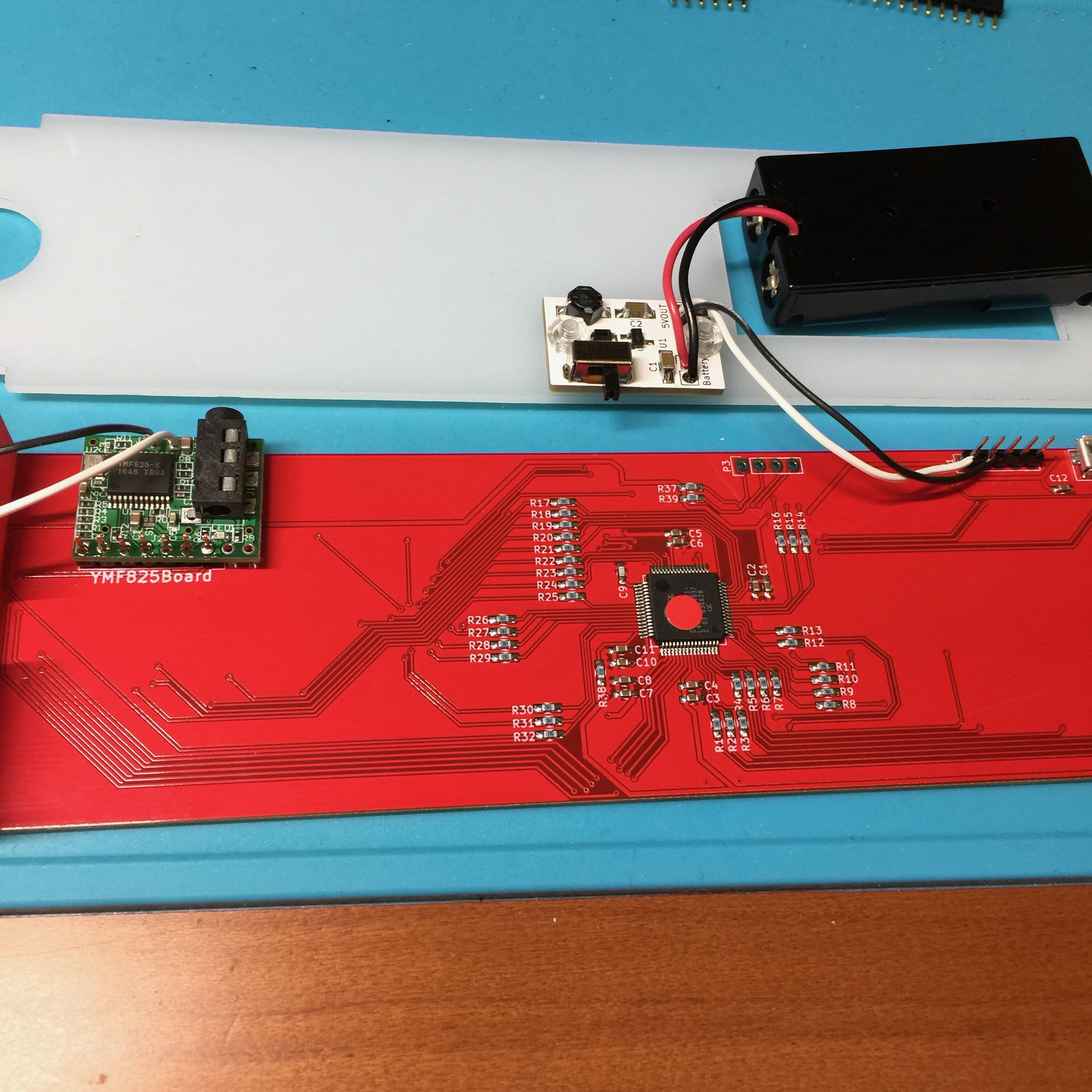
昇圧モジュールを底板にネジ止め
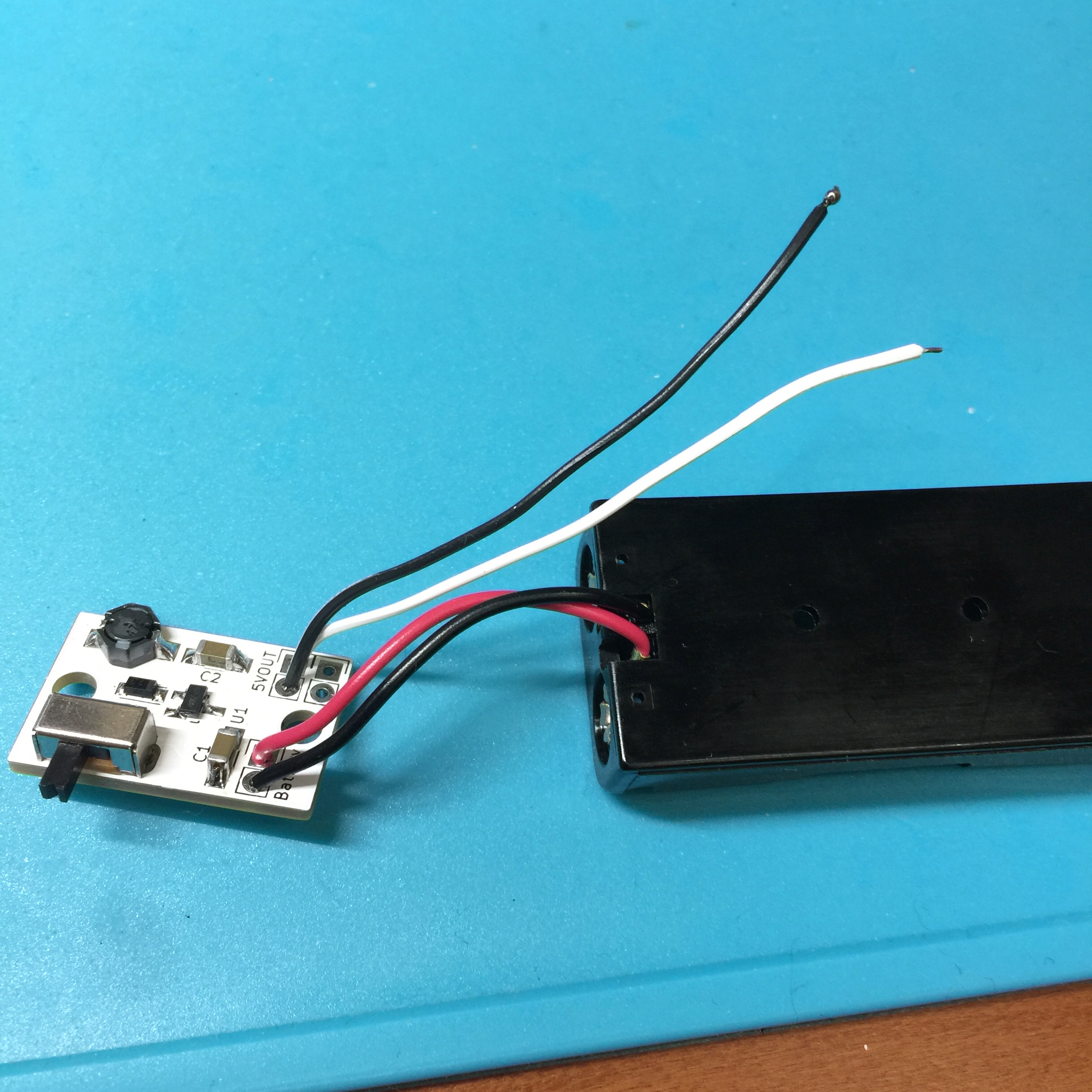
まず、二本のケーブルを7cm程度の長さに切断し、昇圧回路モジュールの5VOUT端子にハンダ付けします。四角い穴が+側で、丸い穴がー側になります。
次に、底板の真ん中ほどに二つのネジ用の穴があるので、そこに昇圧回路モジュールを透明ネジ&ナットでネジ止めします。
Cut two cables to a length of about 7cm and solder it to the 5VOUT terminal of the VCM.
Next, screw up the VCM to the bottom plate with transparent screws and nuts.
TouchMIDI25keyに部品を取り付けよう/Assemble TouchMIDI25key
TouchMIDI25keyにピンヘッダをハンダ付けし、そこにYMF825Board、電源ケーブルをハンダ付けします。
Solder pin headers to TouchMIDI25key and solder the YMF825Board and power cable there.
ピンヘッダのハンダ付け
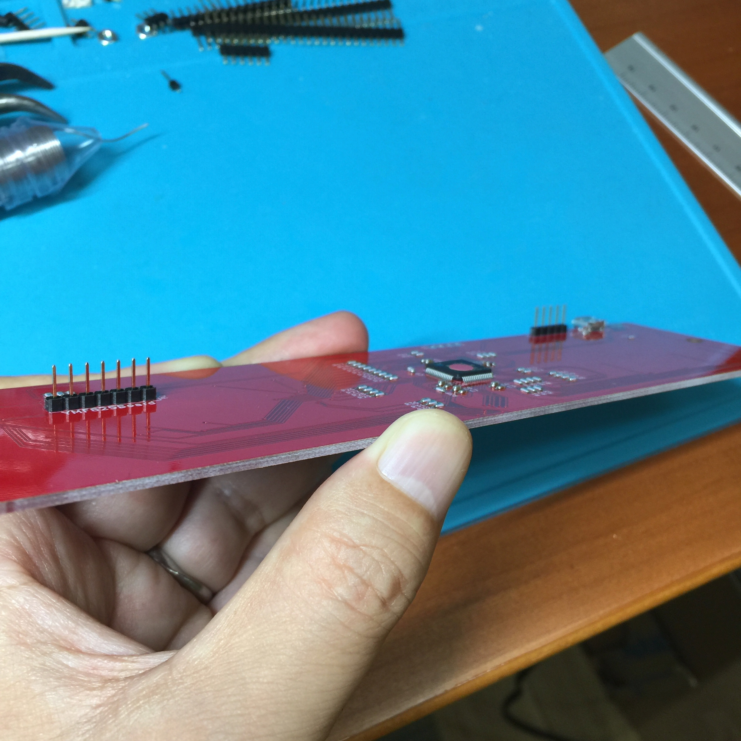
TouchMIDI25keyのP1およびP2にピンヘッダをハンダ付けします。
P1には、直接5V,GNDをハンダ付けするのであれば、ピンヘッダを付ける必要は無いのですが、ピンヘッダを付けておけばPSoCに対してファームウェアを書き換えることが可能となります。
Solder pin headers to P1 and P2 of TouchMIDI25key.
If you attach a pin header, you can rewrite the firmware to PSoC.
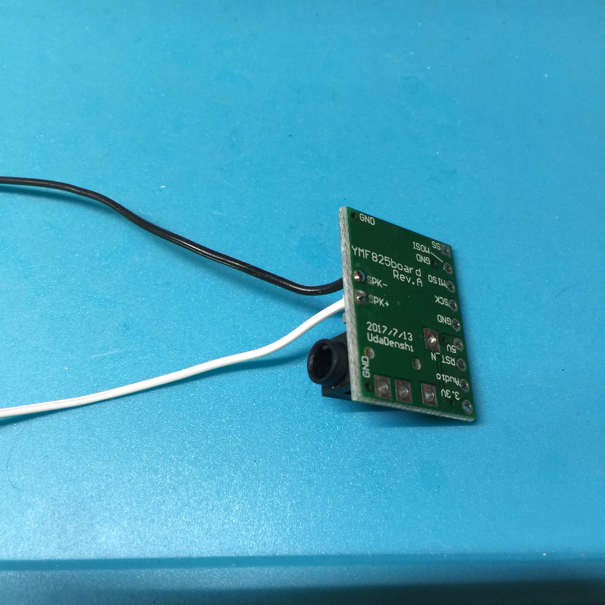
YMF825Boardのハンダ付け
P2のピンヘッダにYMF825Boardをハンダ付けします。
YMF825Boardの3.3V端子、及びAudio端子の二本は繋げず、残りの7つの端子とピンヘッダをハンダ付けします。
Solder YMF825Board to P2 pin header.
Do not connect the 3.3V terminal and the audio terminal of the YMF825Board, and solder the remaining seven terminals and pin headers.
電源ケーブルのハンダ付け
昇圧回路モジュールにハンダ付けした電源用ケーブルを、P1の電源、GNDにハンダ付けします。
P1のCPU側の端子が5V電源、次の端子がGNDとなります。
Solder the power supply cable soldered to the VCM to the P1 power supply and GND.
The terminal on the CPU side of P1 is 5V power supply, the next terminal is GND.
全体を組み立てよう/Assemble all parts
スピーカー付き台座、昇圧モジュール付き底板、TouchMIDI25keyを組み立てます。
The support with speaker, the bottom plate with the VCM, TouchMIDI25key are assembled.
The support with speaker, the bottom plate with the VCM, TouchMIDI25key are assembled.
台座のネジ止め
3Dプリントによる左右の台座をTouchMIDI25keyにネジ止めします。透明ネジと透明ナットを使います。
Screw the left and right supports by 3D-print to the TouchMIDI25key. Use transparent screws and transparent nuts.
Screw the left and right supports by 3D-print to the TouchMIDI25key. Use transparent screws and transparent nuts.
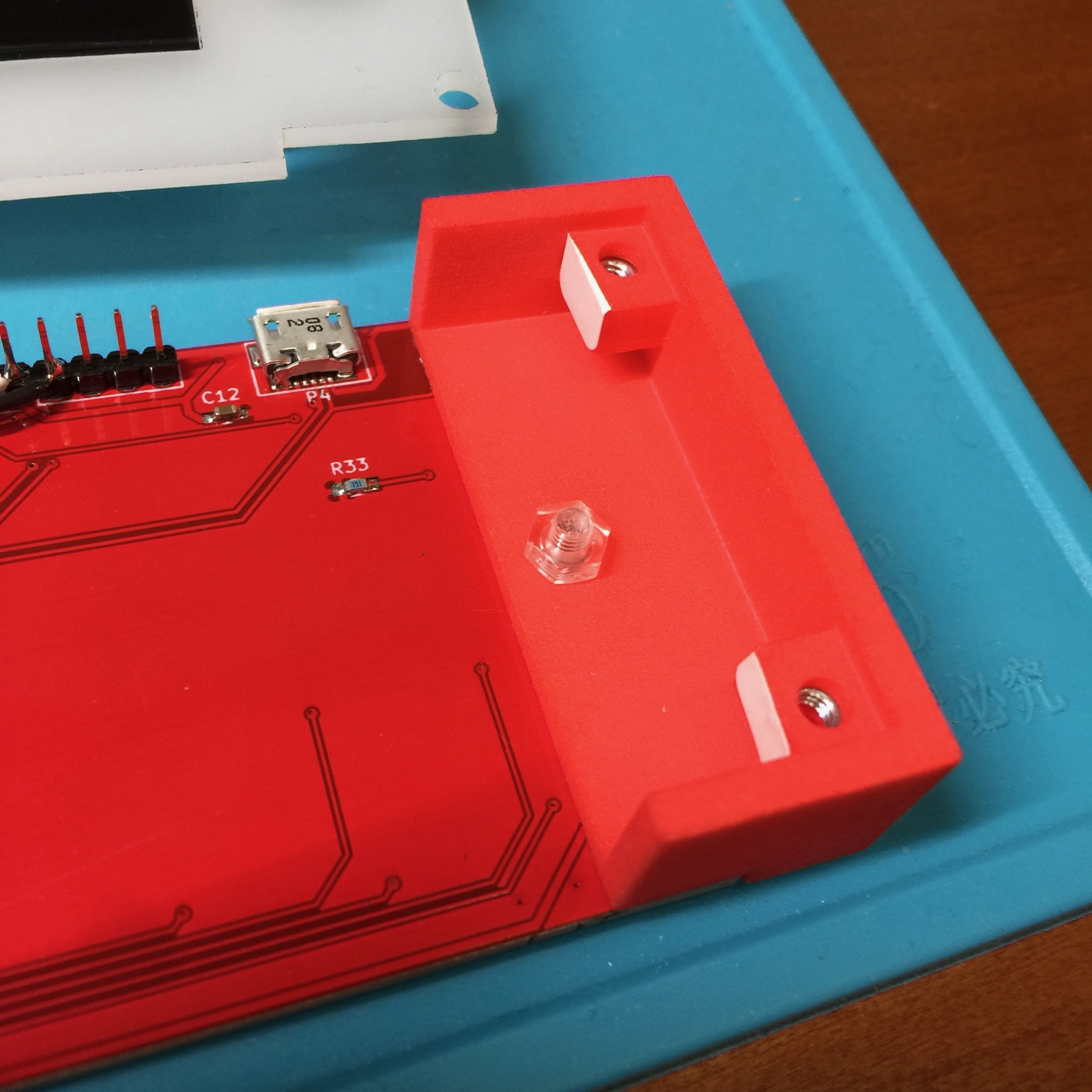
底板のネジ止め
アクリル板の底板の4スミを、4つの透明ネジでネジ止めします。
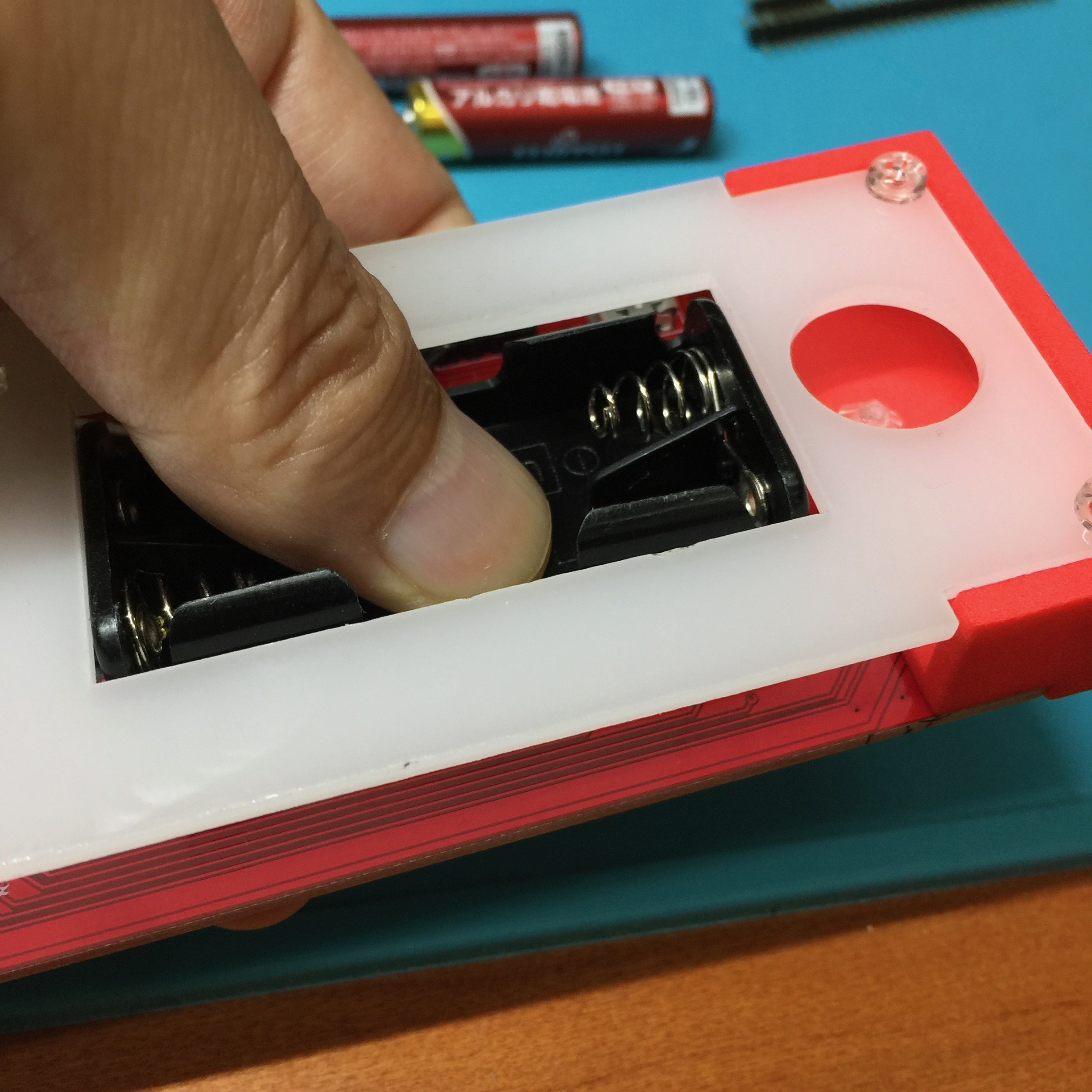
最後に、電池ボックスを両面テープで基板に貼り付けます。
Screw 4 corners on the bottom plate of the acrylic plate with four transparent screws.
Finally, attach the battery box to the board with double-sided tape.