
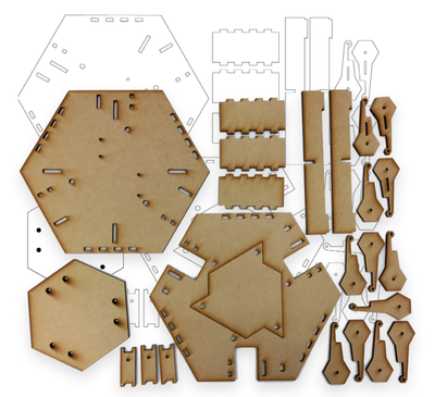
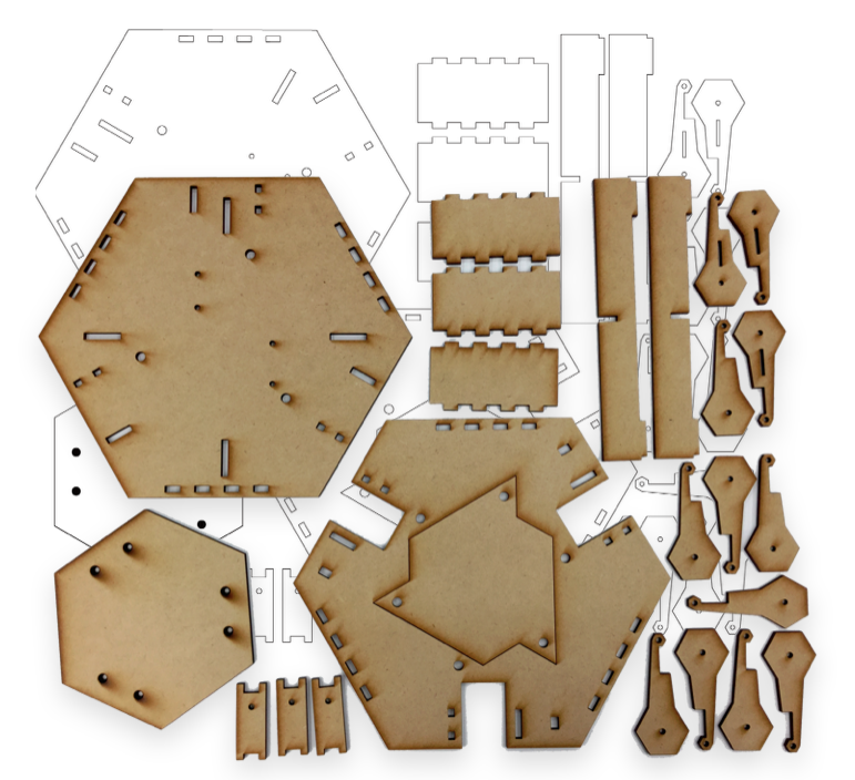
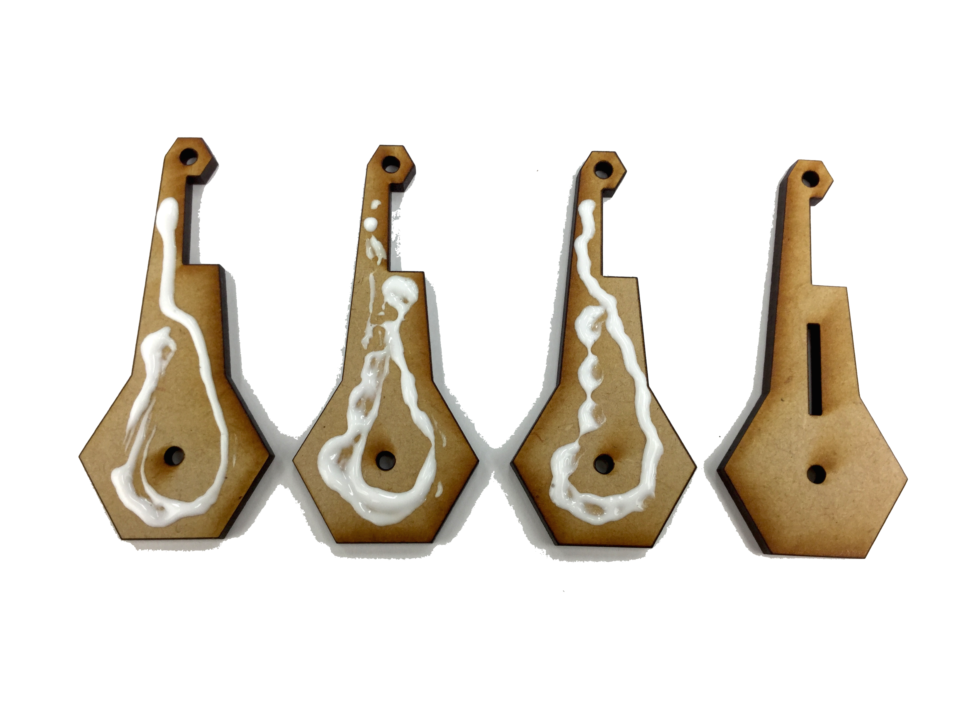
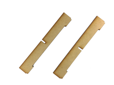
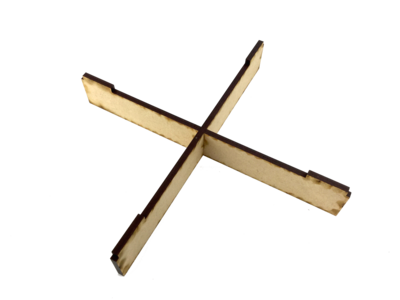
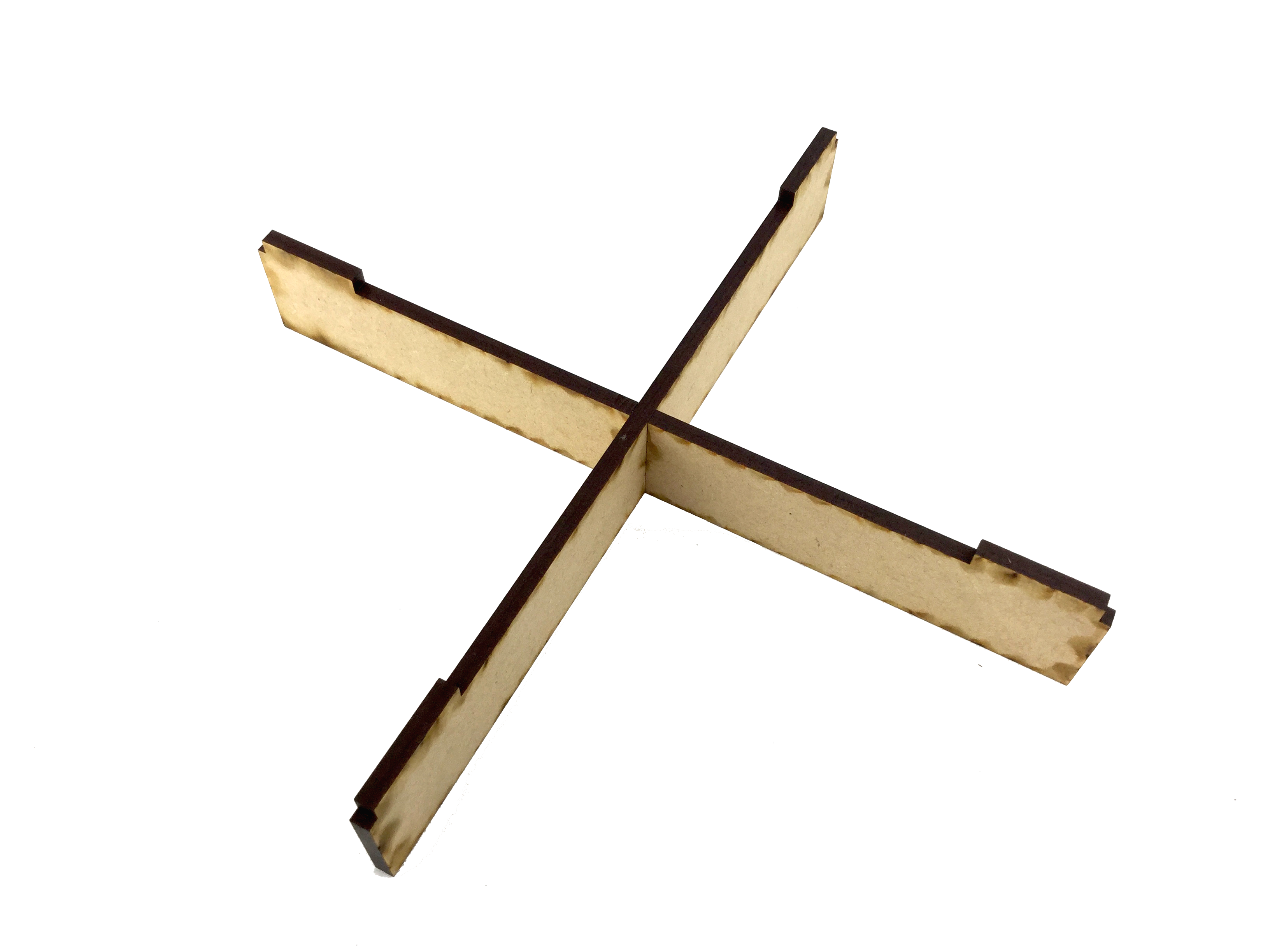
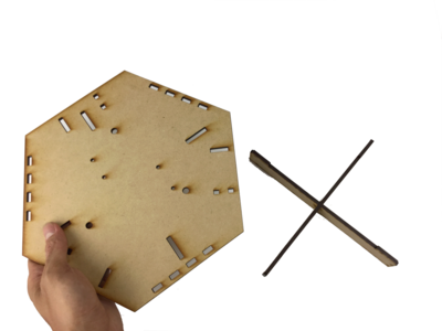
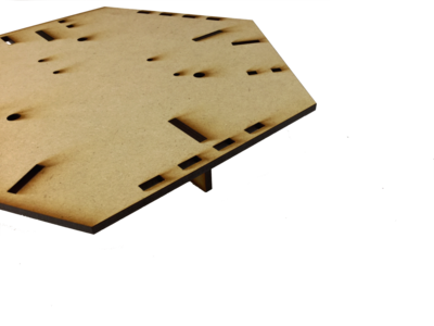
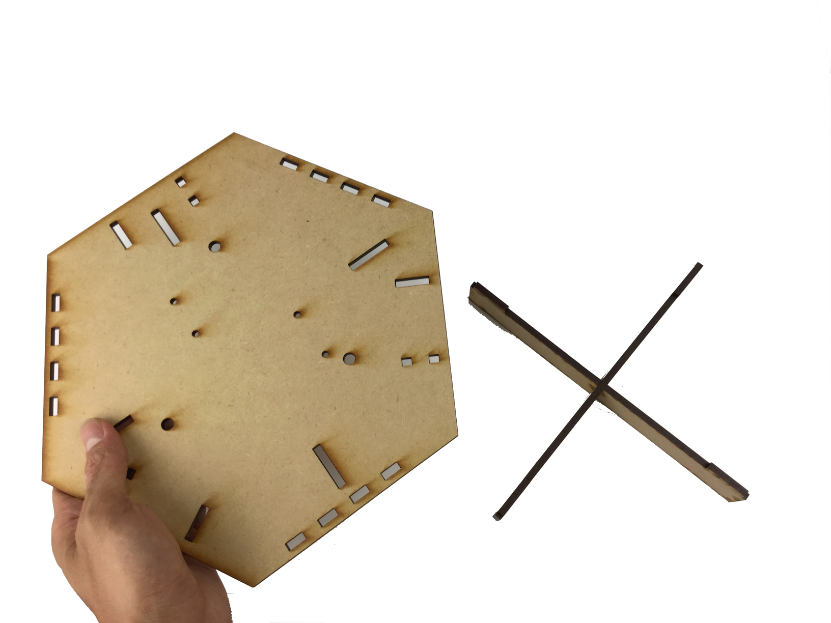
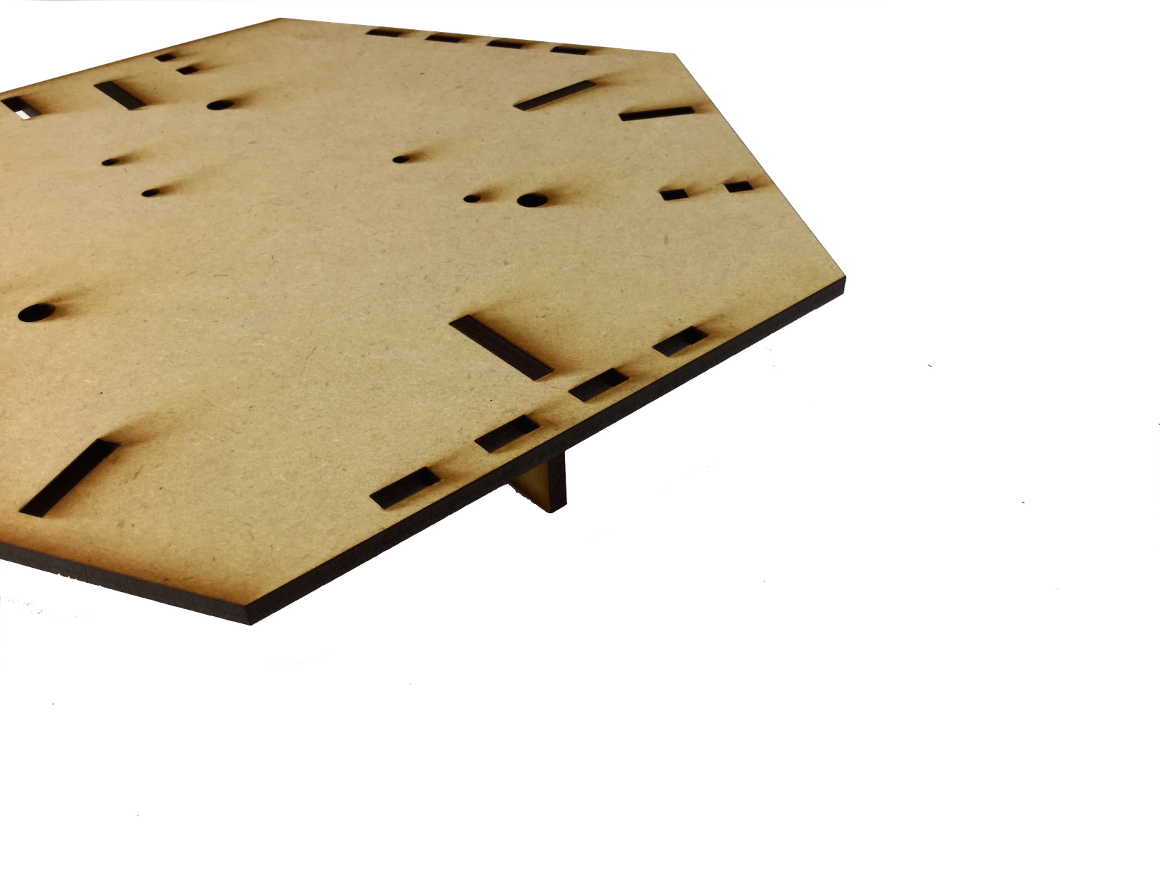
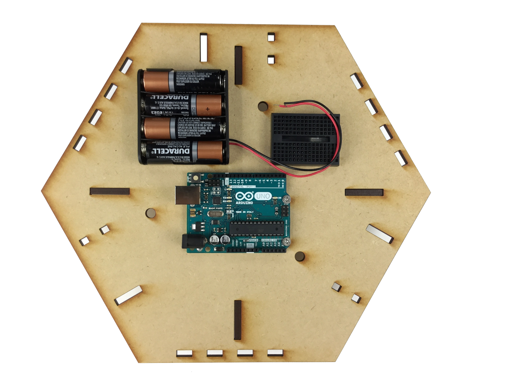
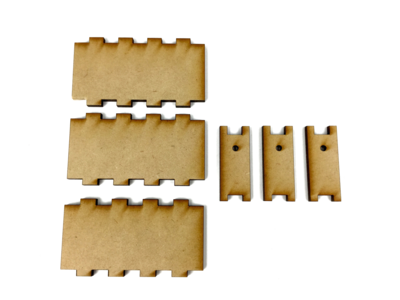
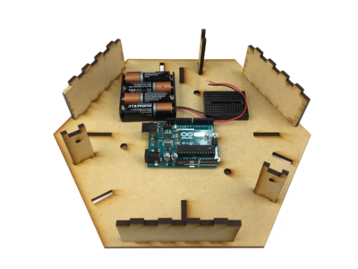
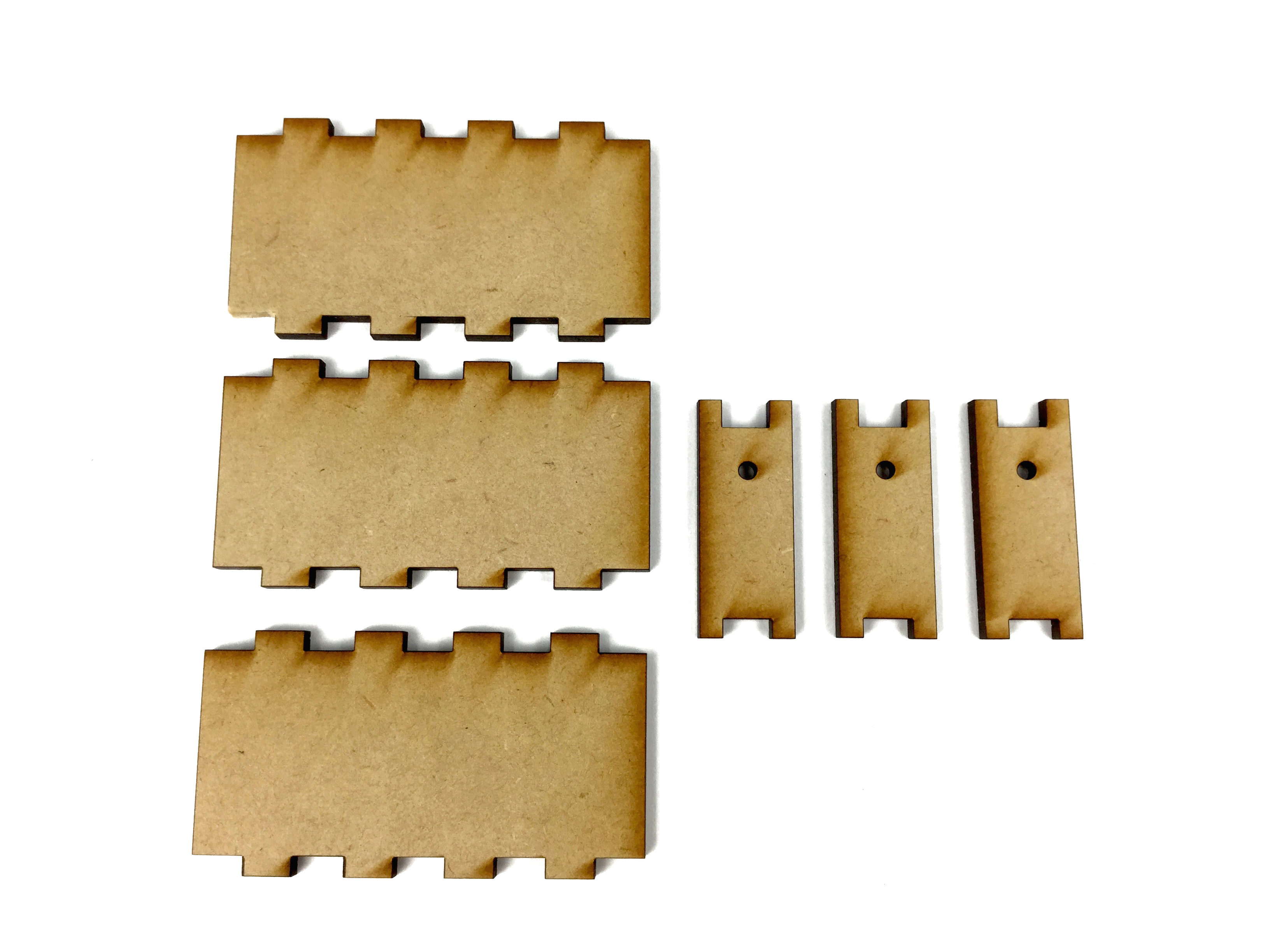
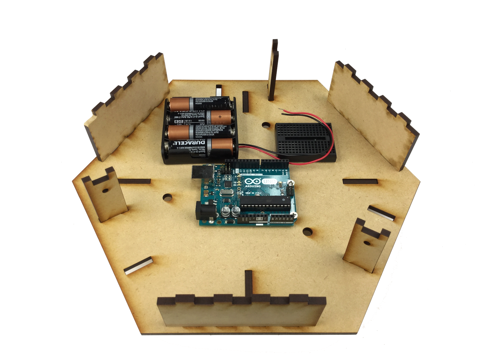
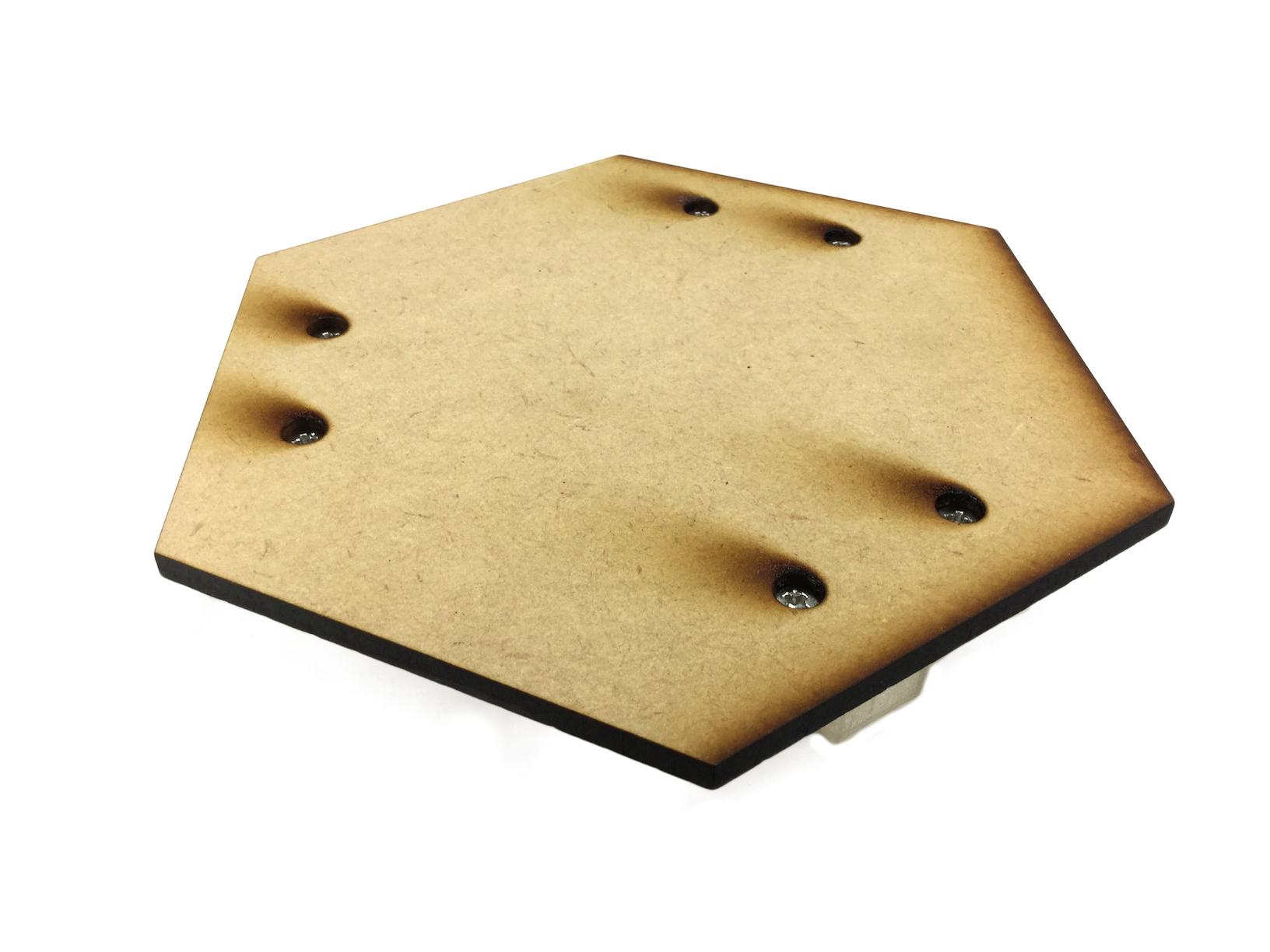
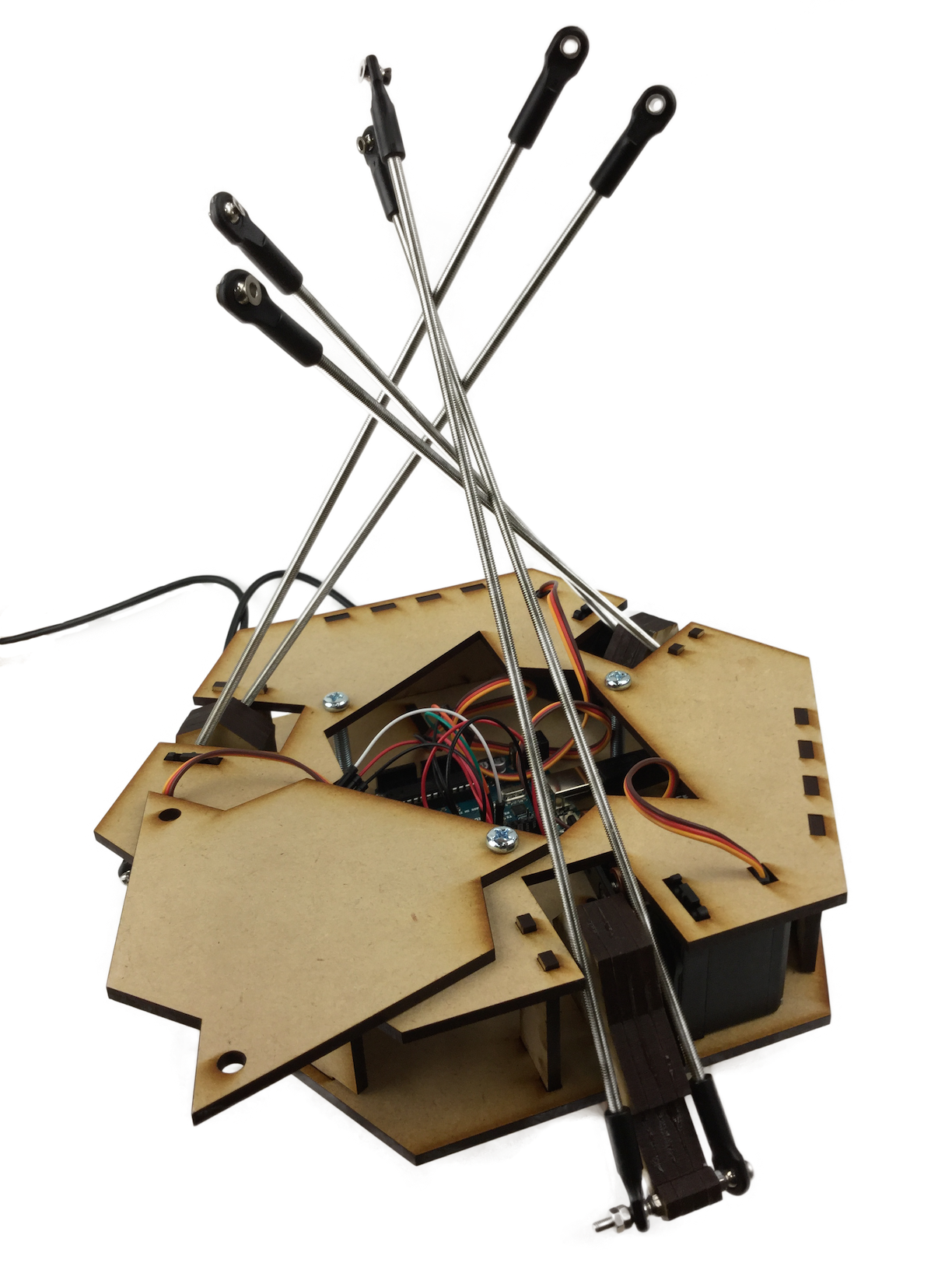
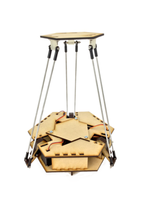
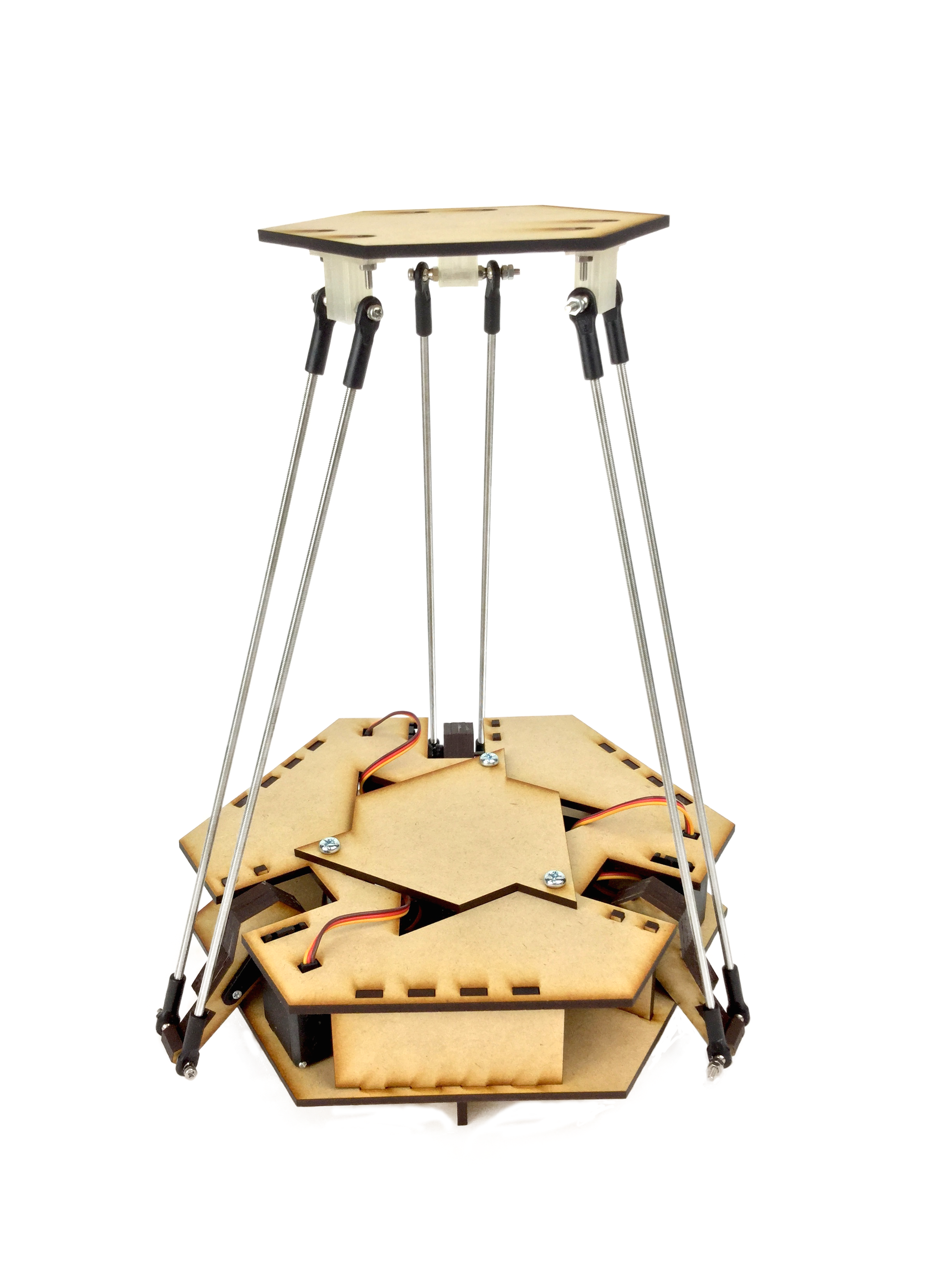
MDF board (4mm 600*450mm) *1
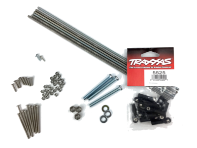
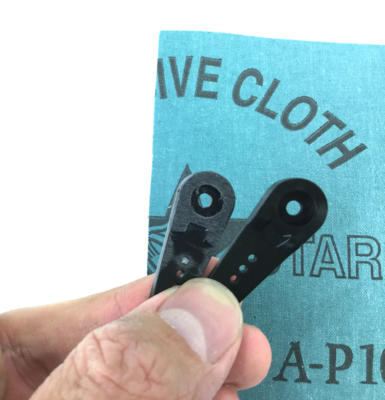
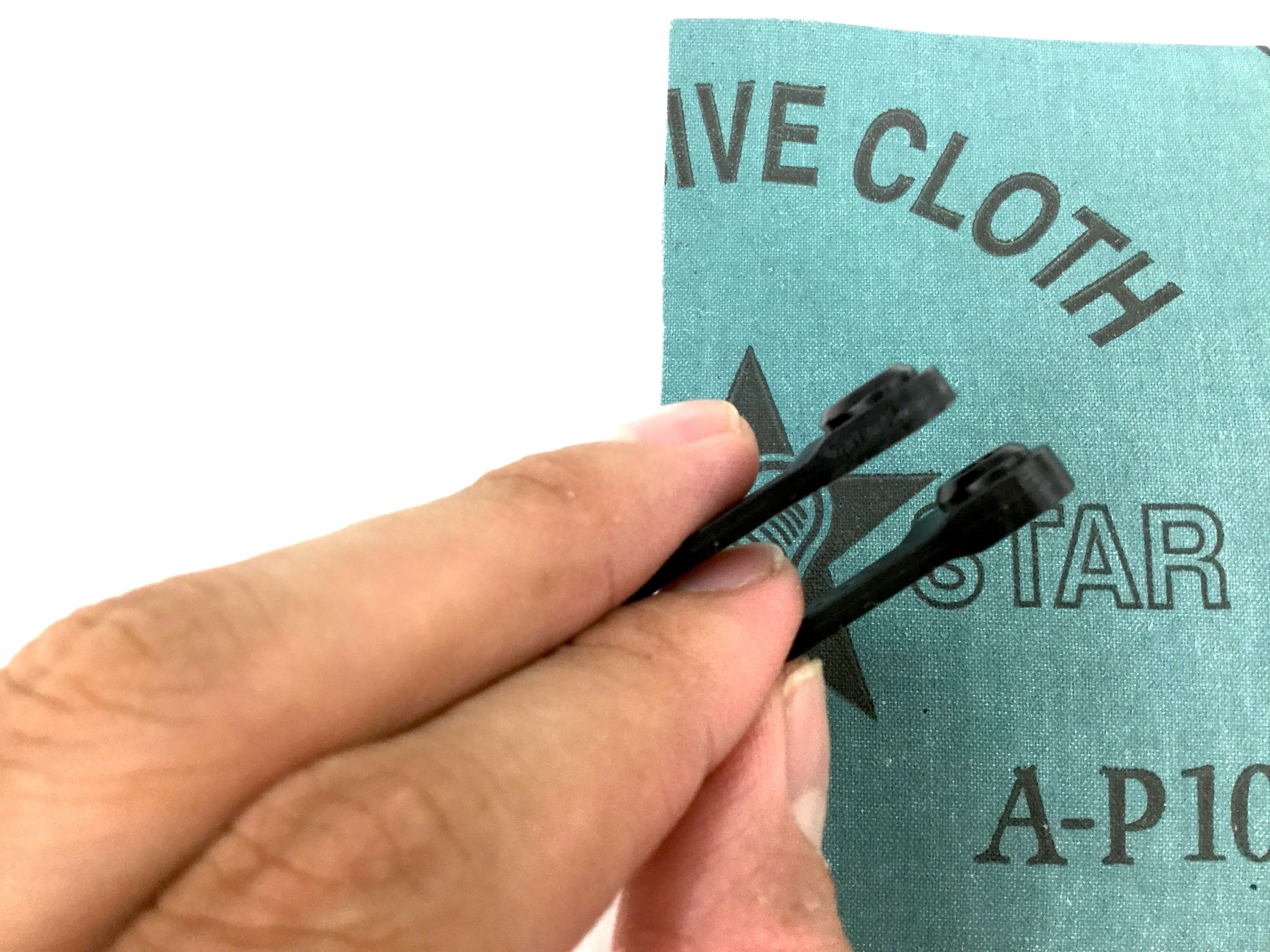
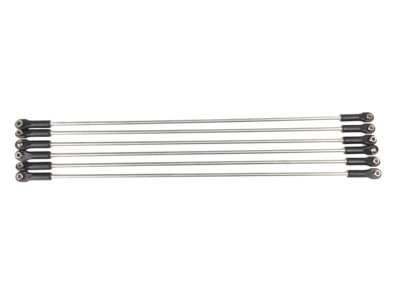
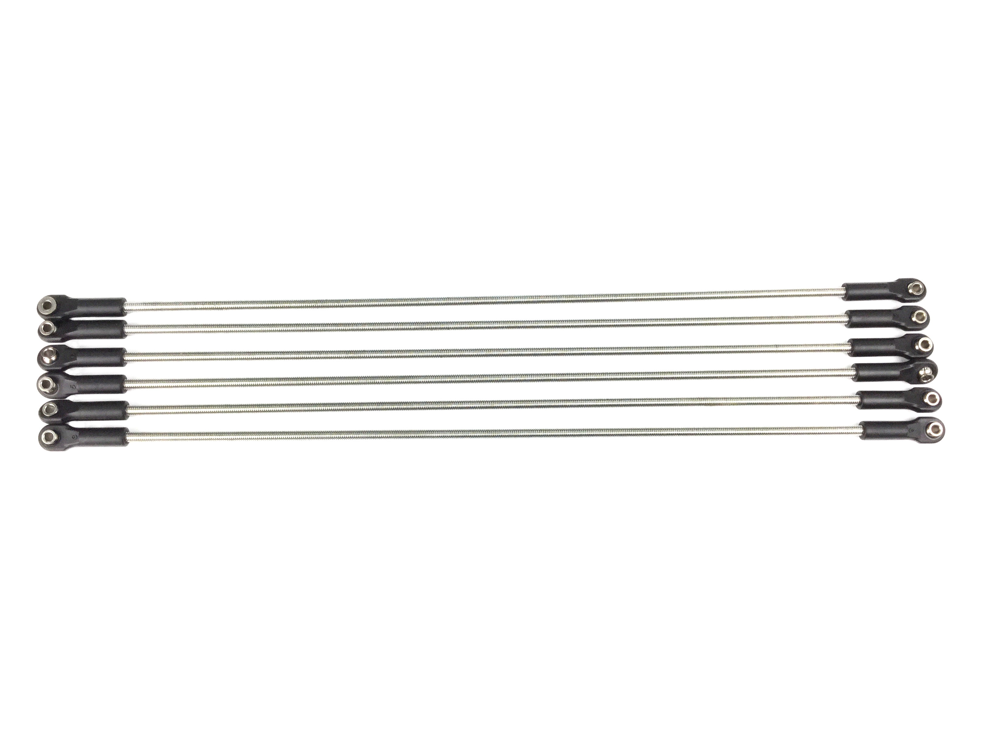
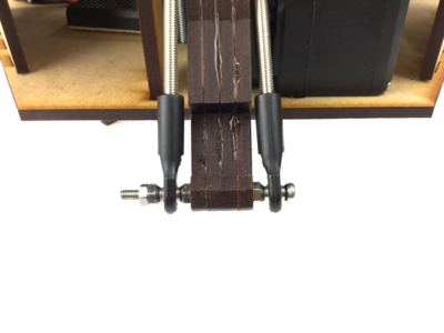
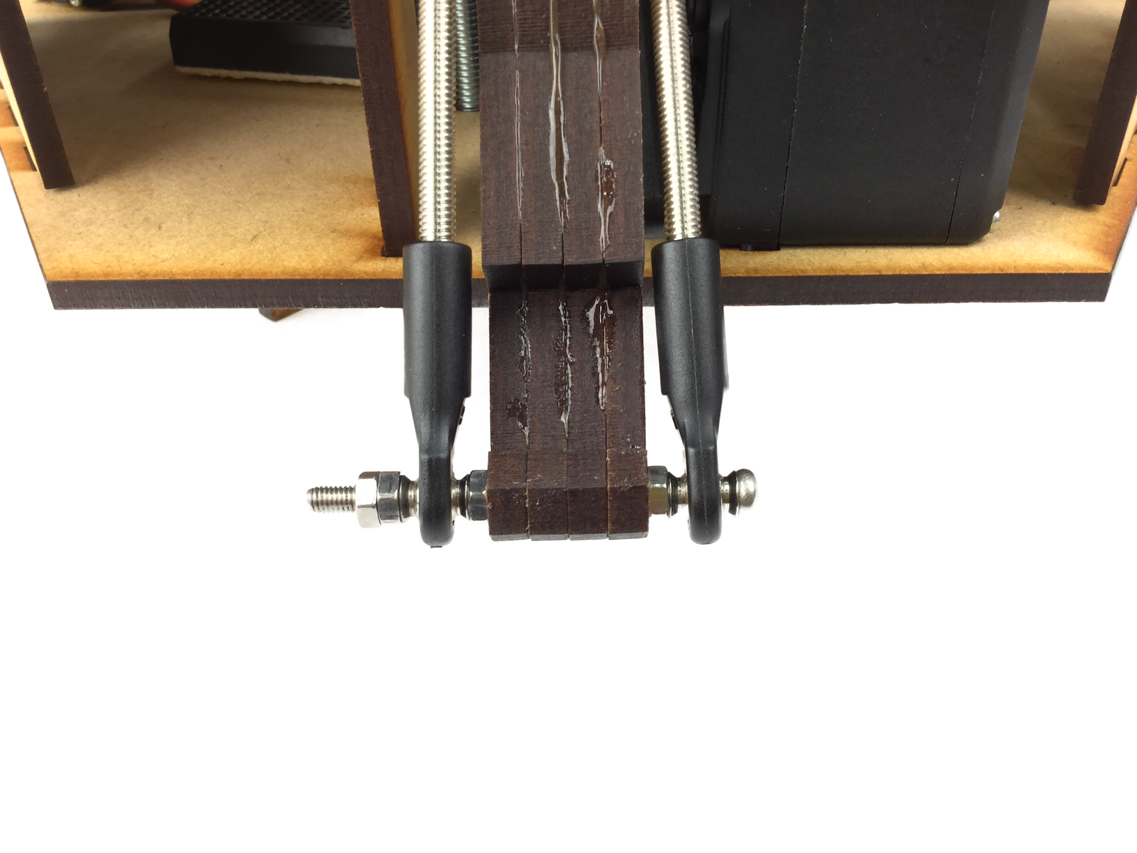
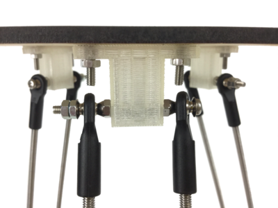
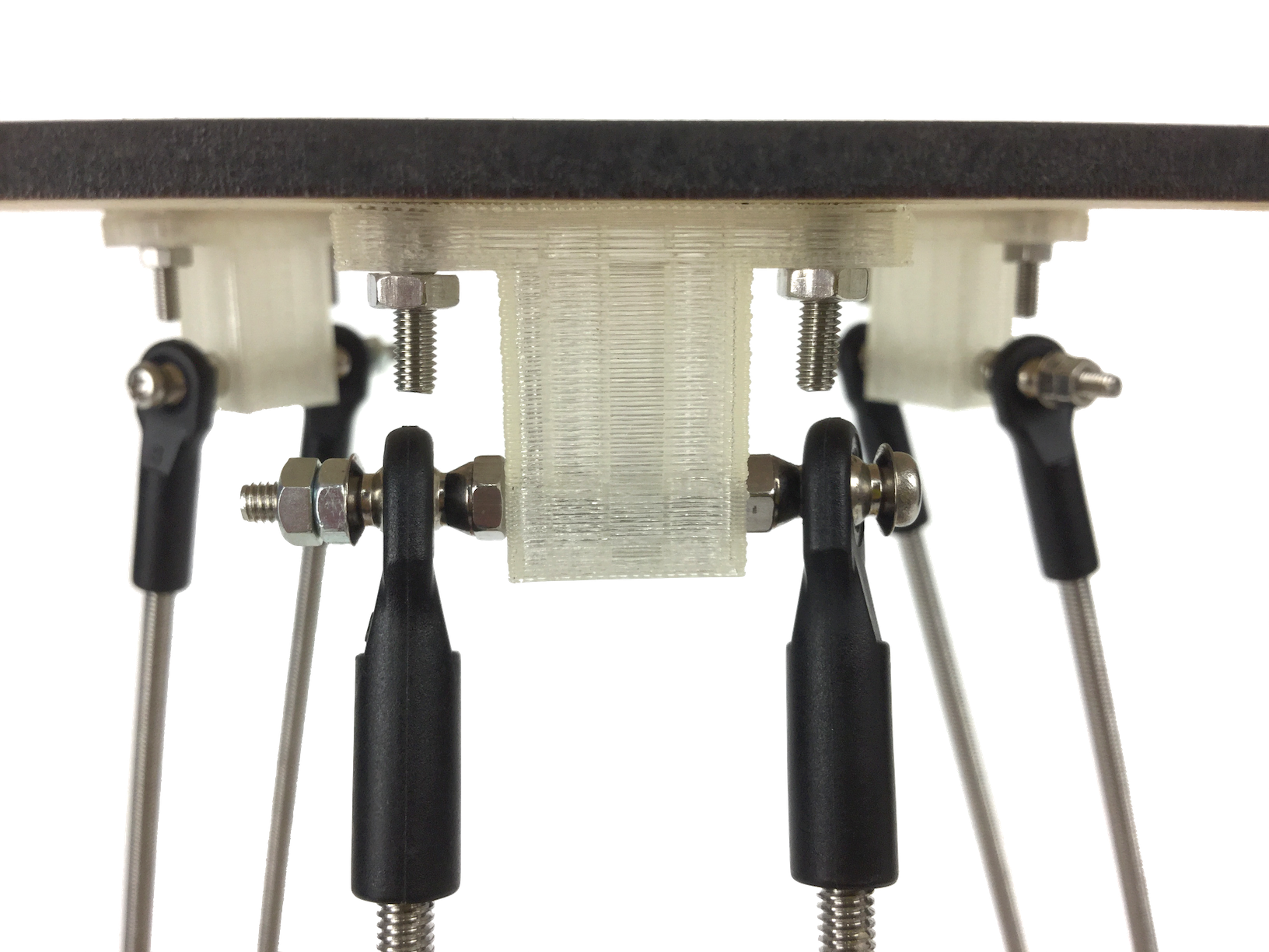
Rod ends (TRAXXAS #5525 12 pieces)*1
[Screws]
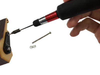
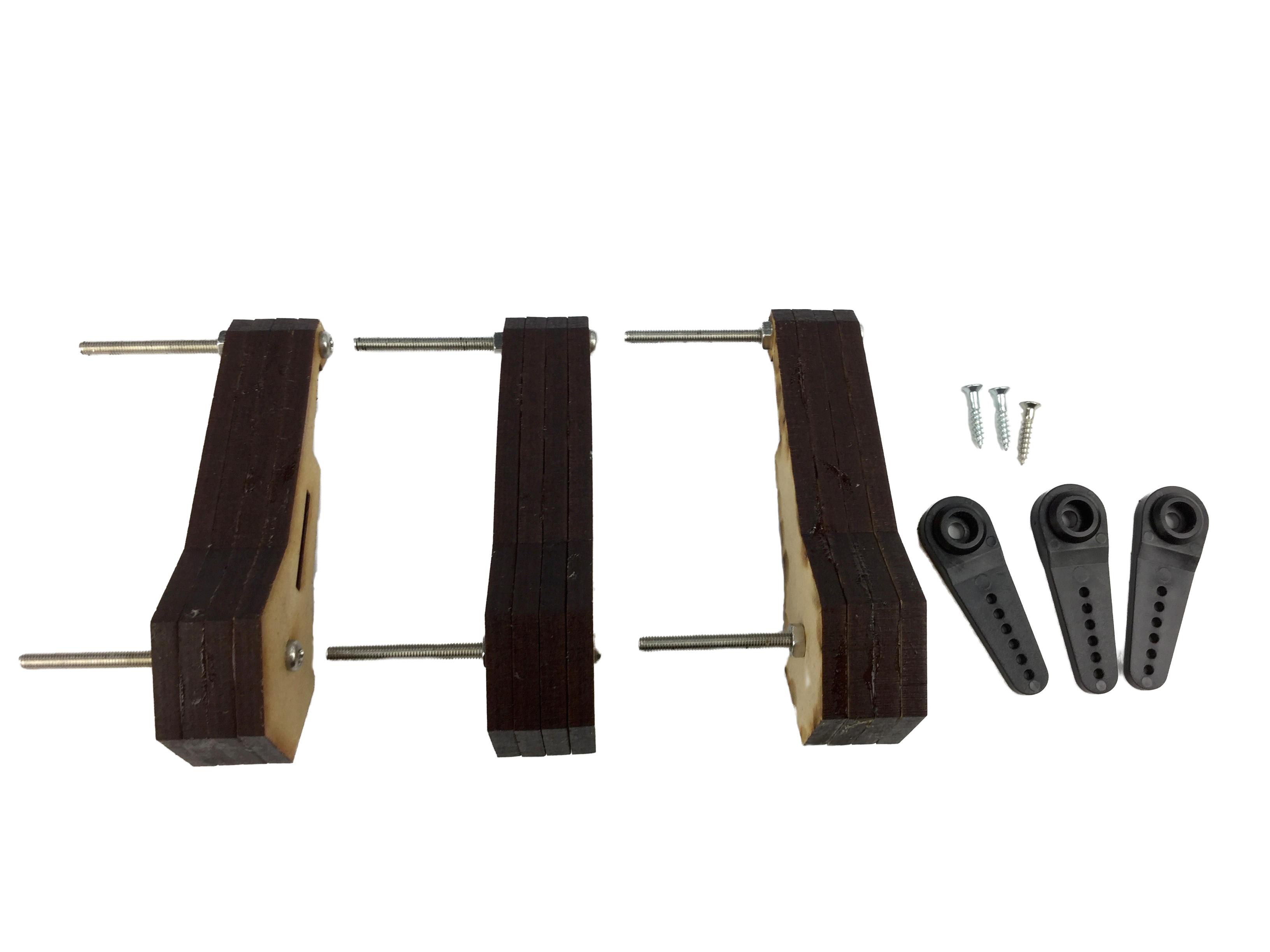
M2.1 Wood 13mm *3
M3 Flat-head 15mm *8
M3 Pan-head 45mm *9
M3 Nuts *34
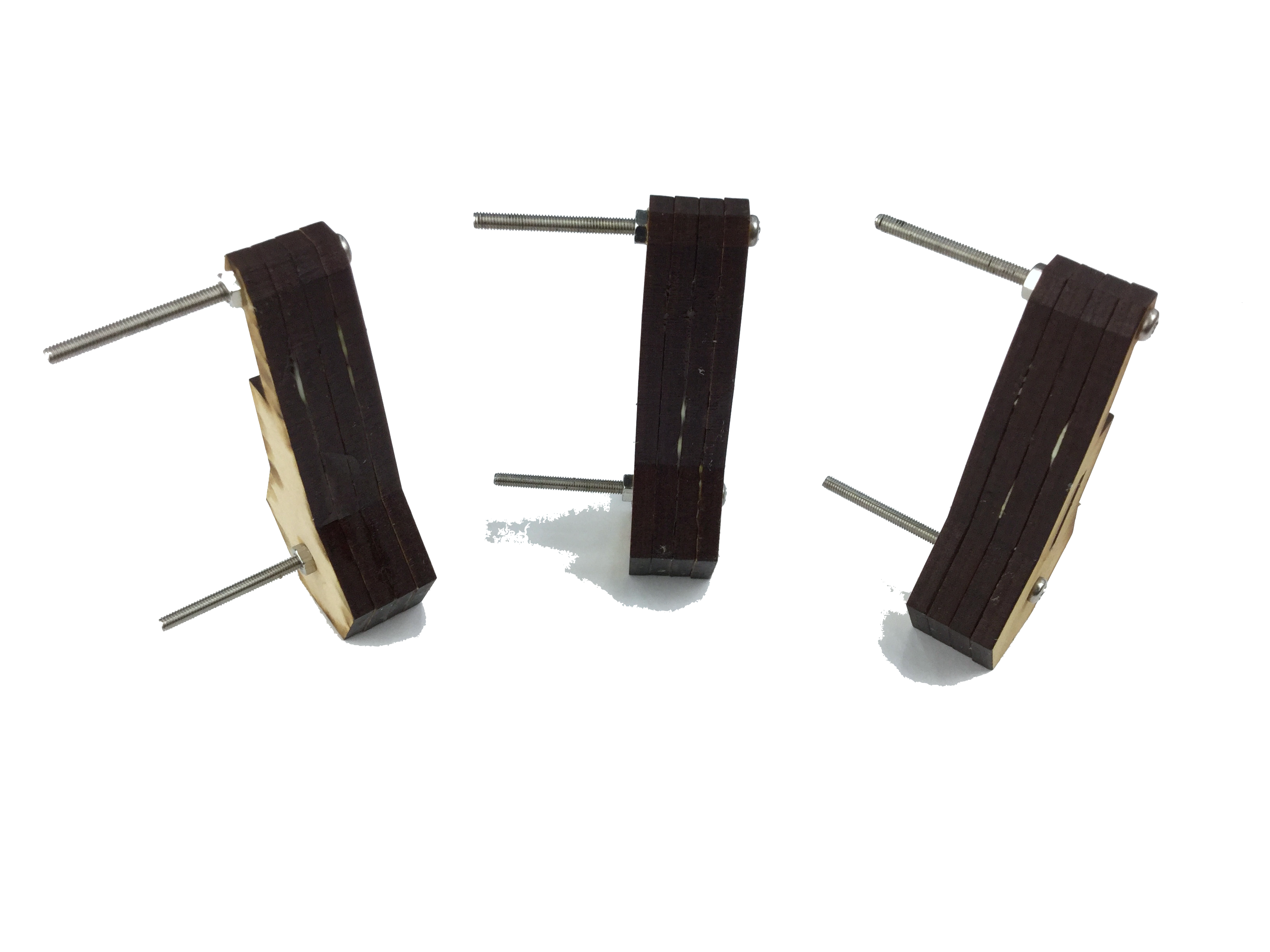
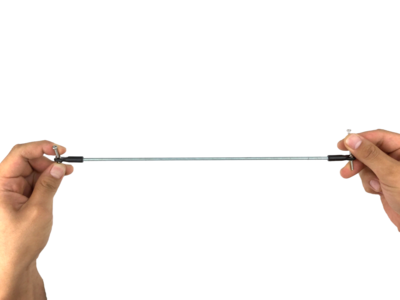
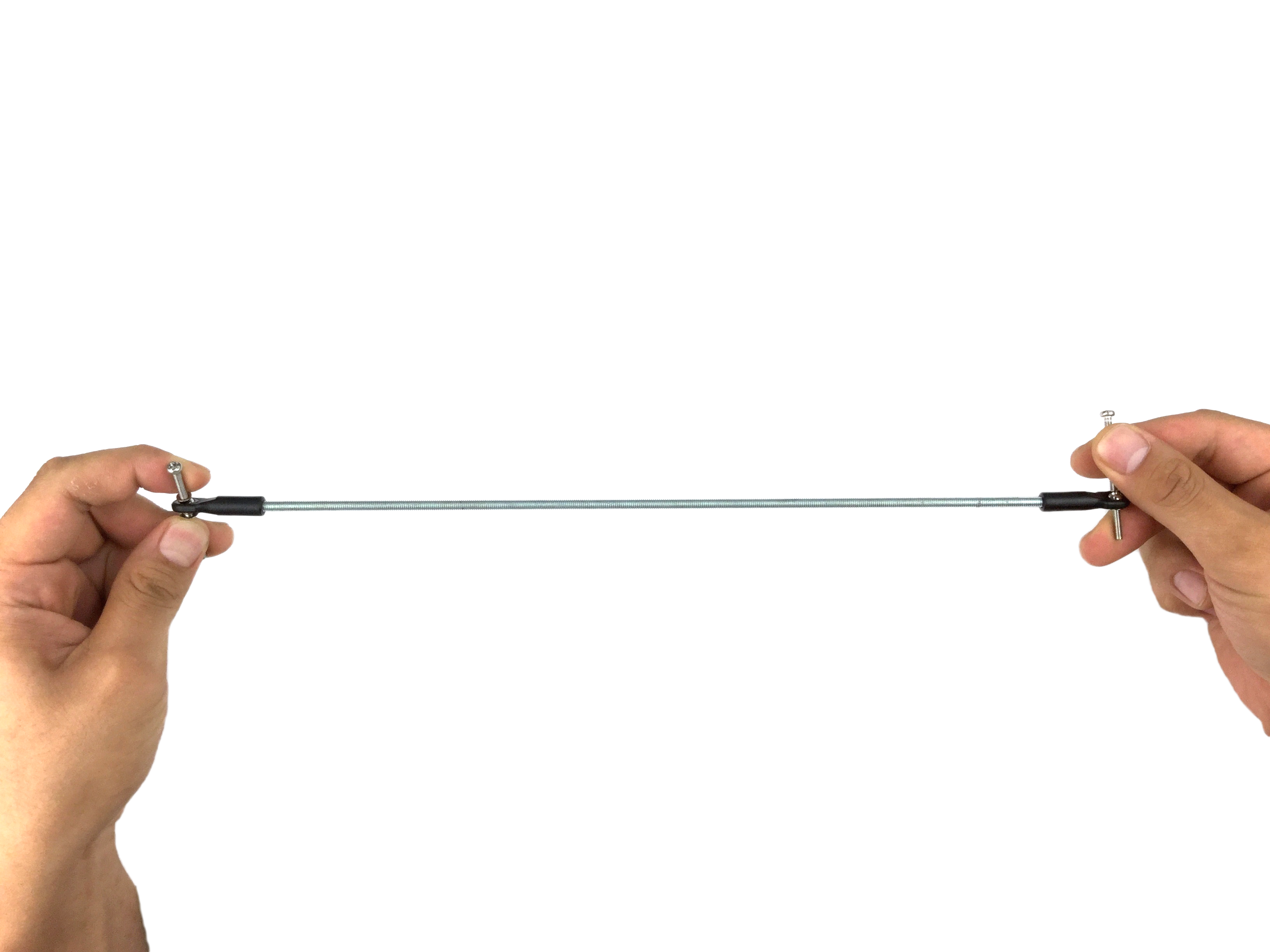
M4 Threaded rods 285mm *6
M6 Pan-head *3
M6 Nuts *3
M6 Washers *3
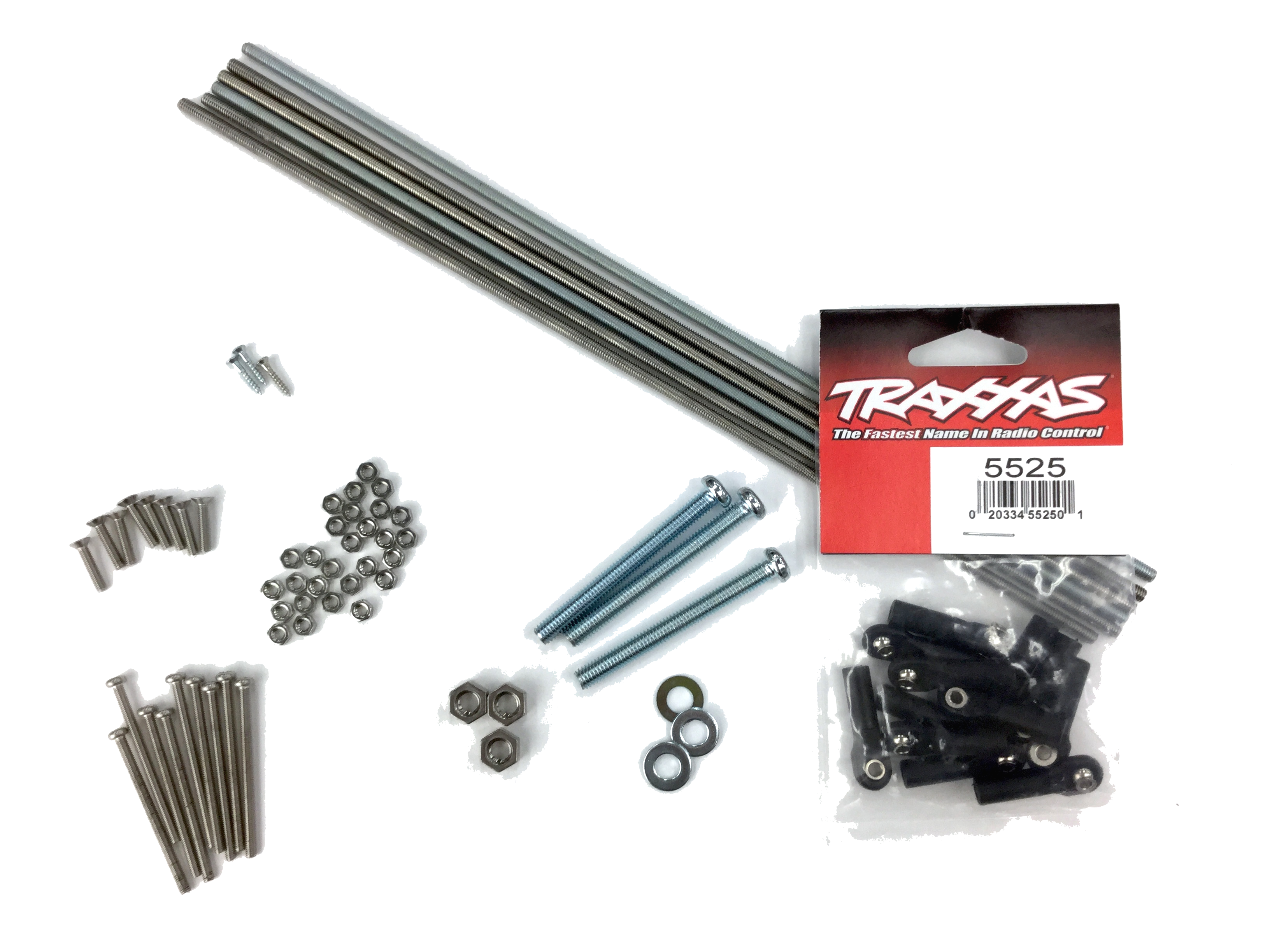
Rod ends (TRAXXAS #5525 12 pieces)*1
[Screws]
M2.1 Wood 13mm *3
M3 Flat-head 15mm *8
M3 Pan-head 45mm *9
M3 Nuts *34
M4 Threaded rods 285mm *6
M6 Pan-head *3
M6 Nuts *3
M6 Washers *3


Comments