

以下の商品をご購入ください
Prepare those three products below:
・ポータブルFM音源キーボード製作キット(全部入り)
(Portable FM Tone Generator Assembly Kit)
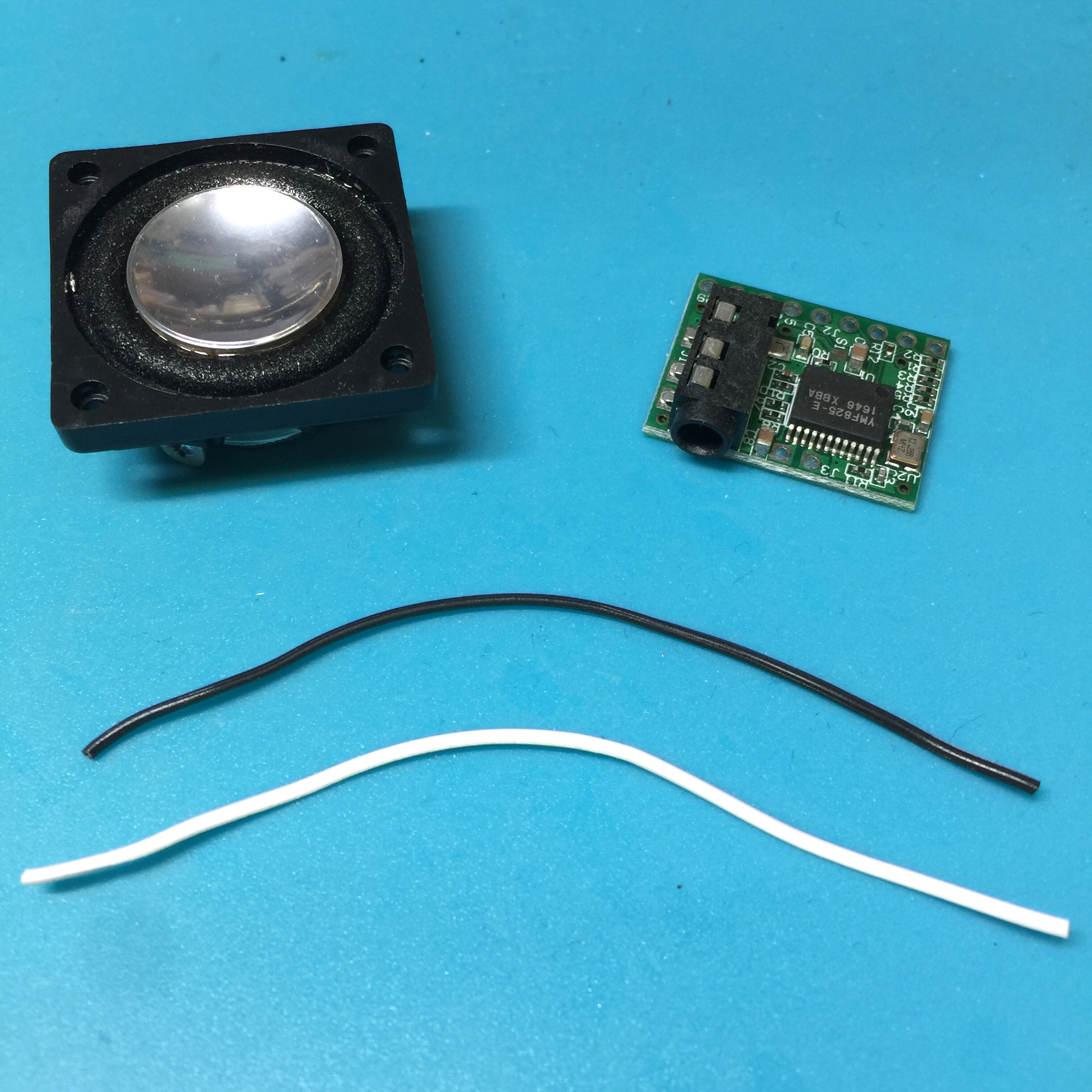
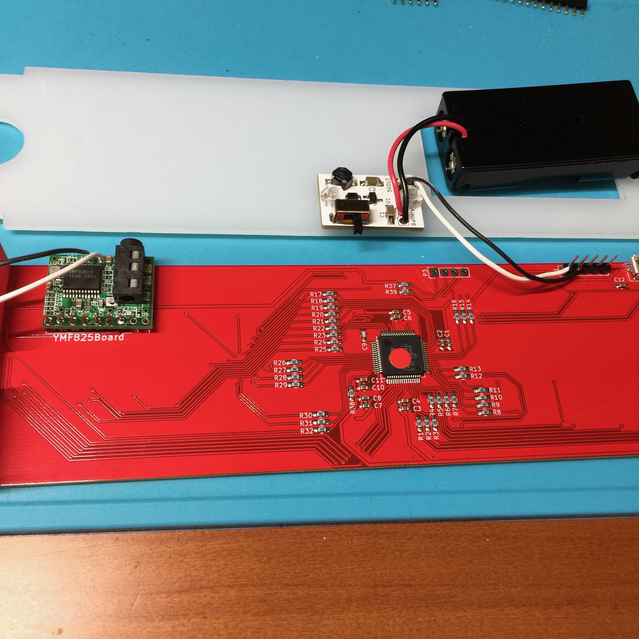
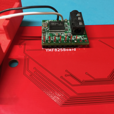
- 製作に必要な部品を全部入りキットとして販売しております。本キットは奇楽堂のネットショップにて扱います。全部入りキットには写真の部品他、TouchMIDI25key、YMF825Boardが入っています。

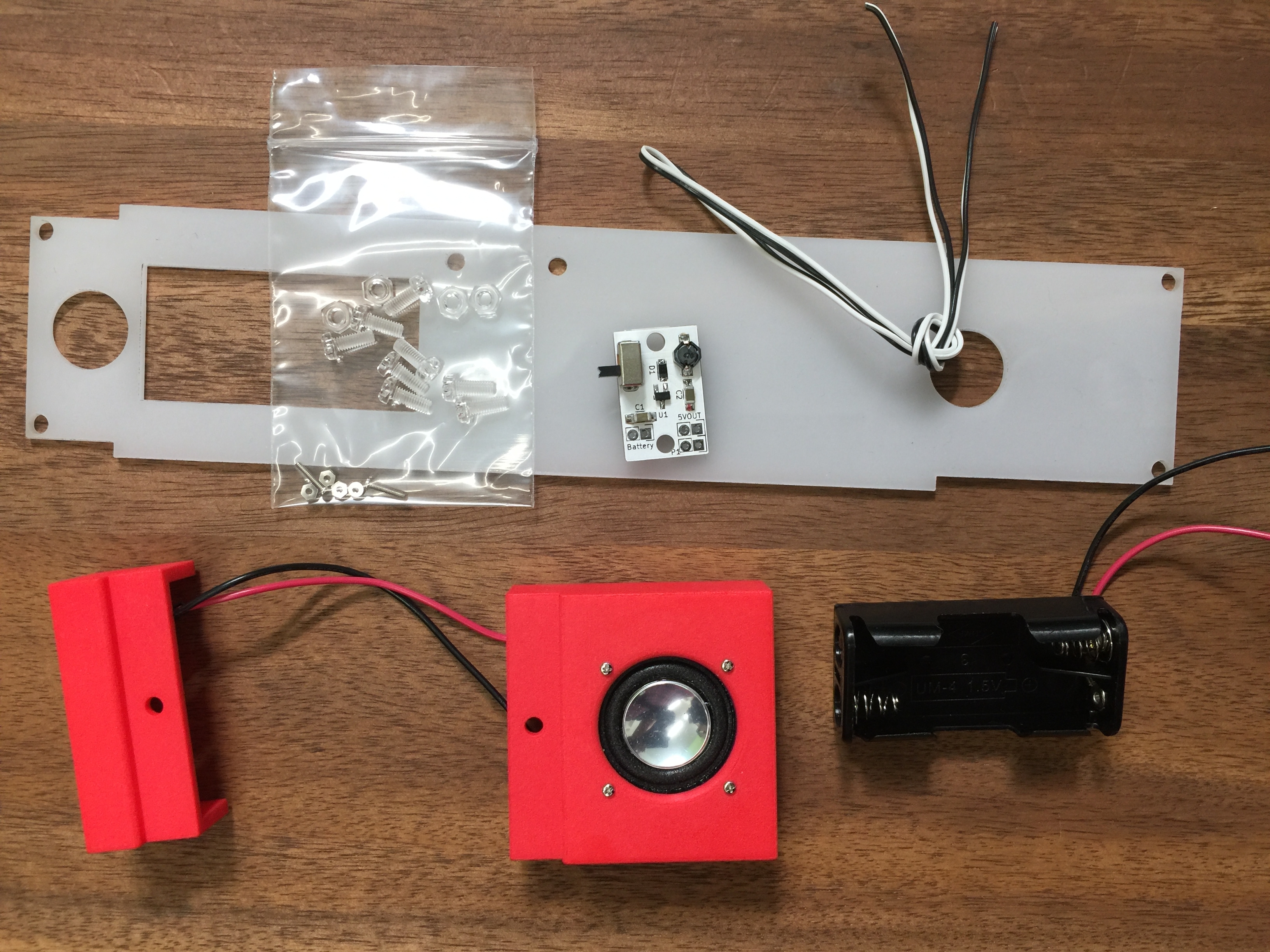
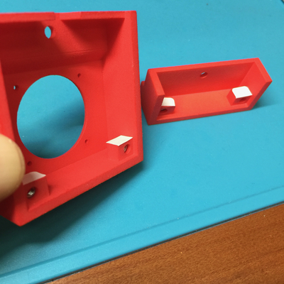
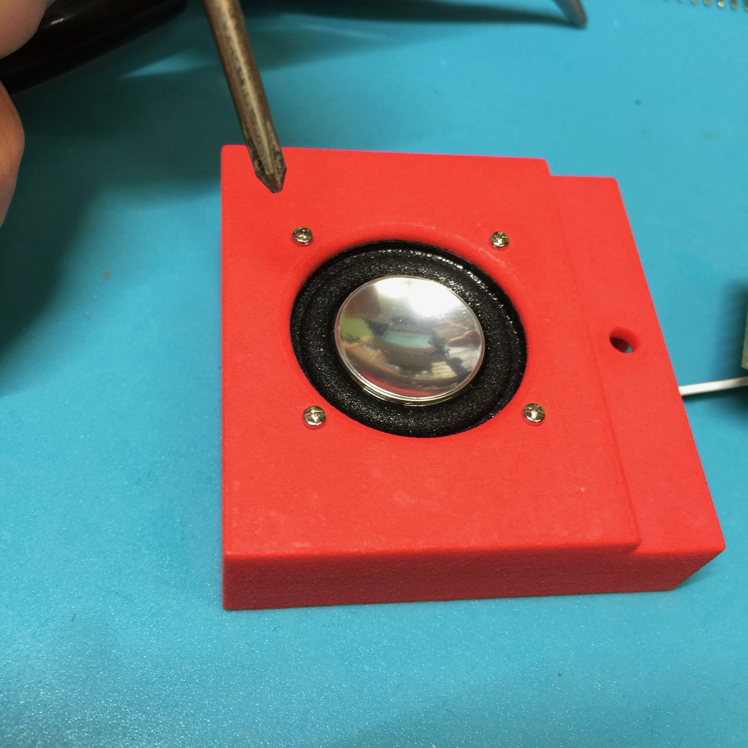
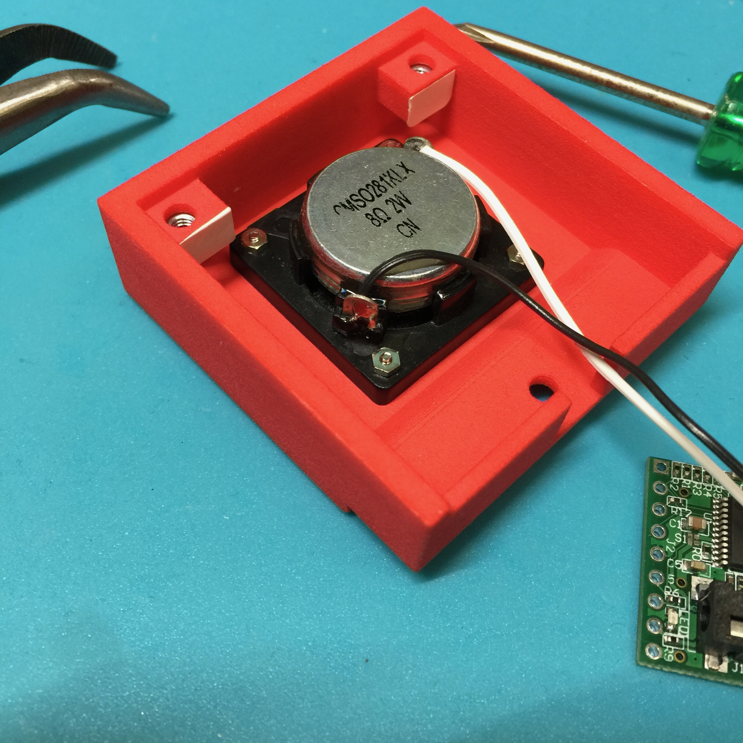
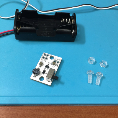
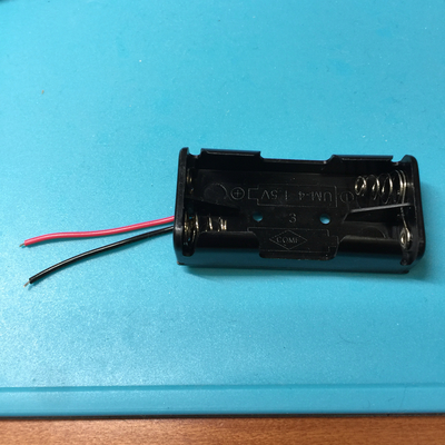
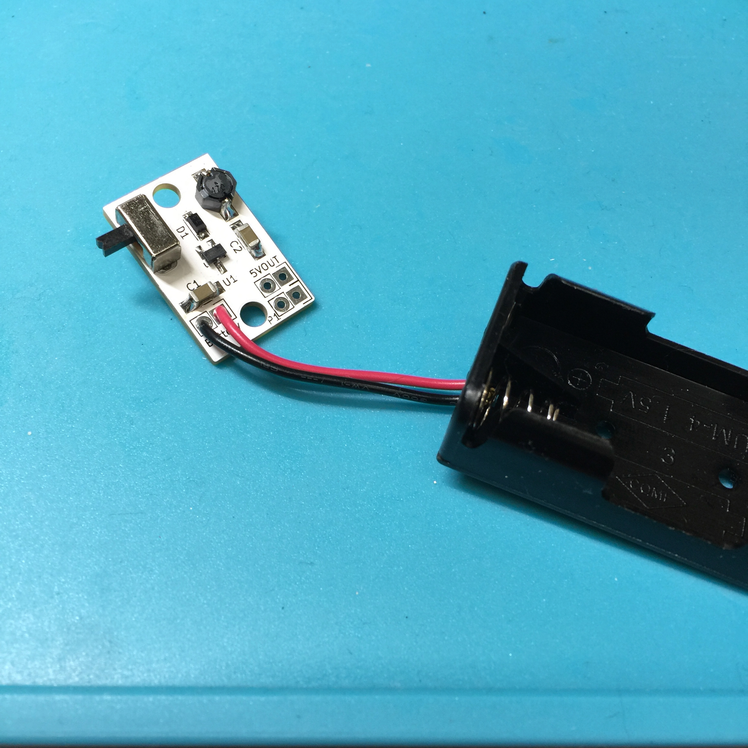
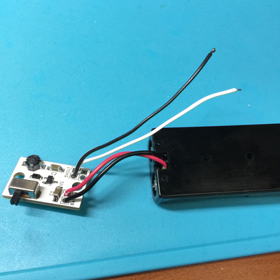
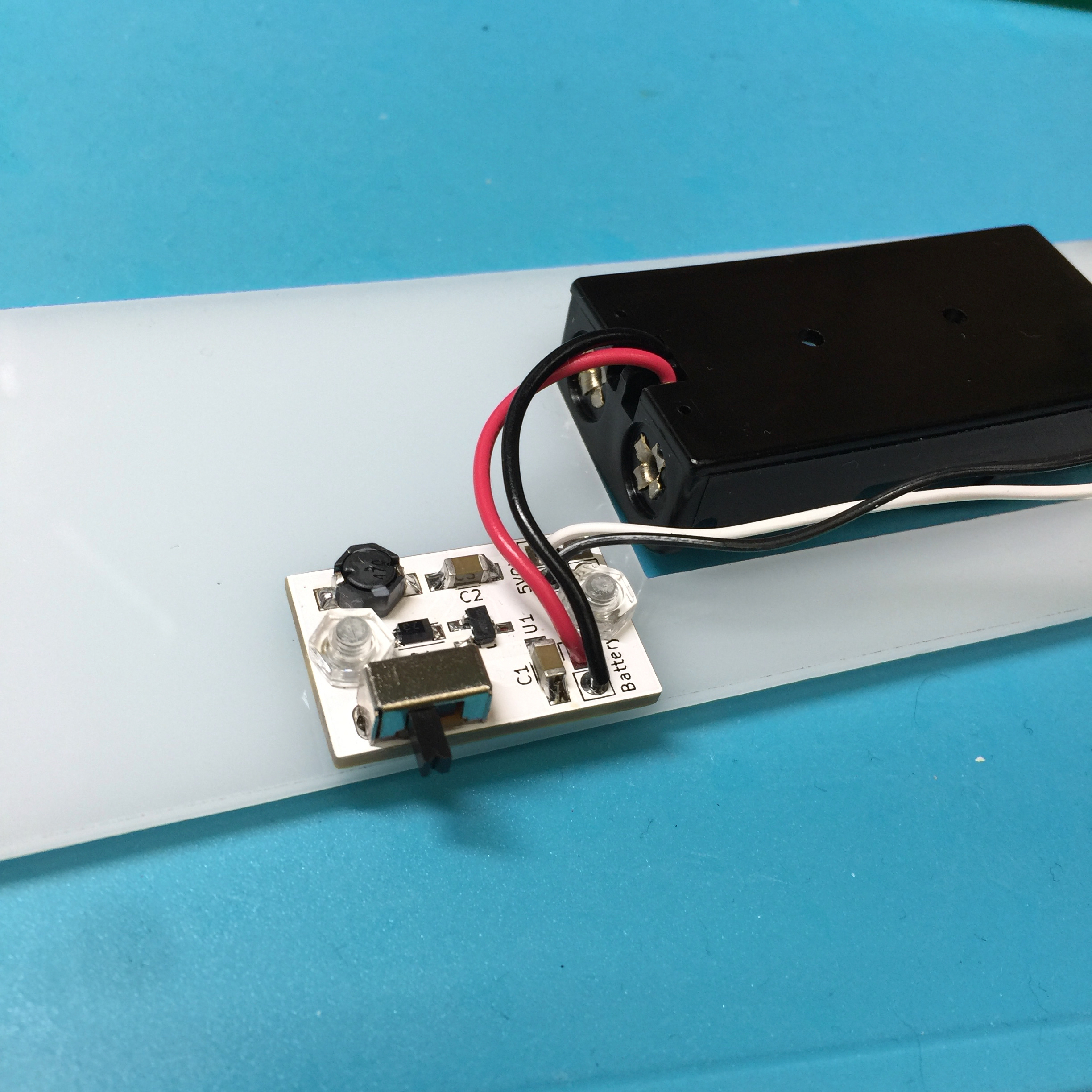
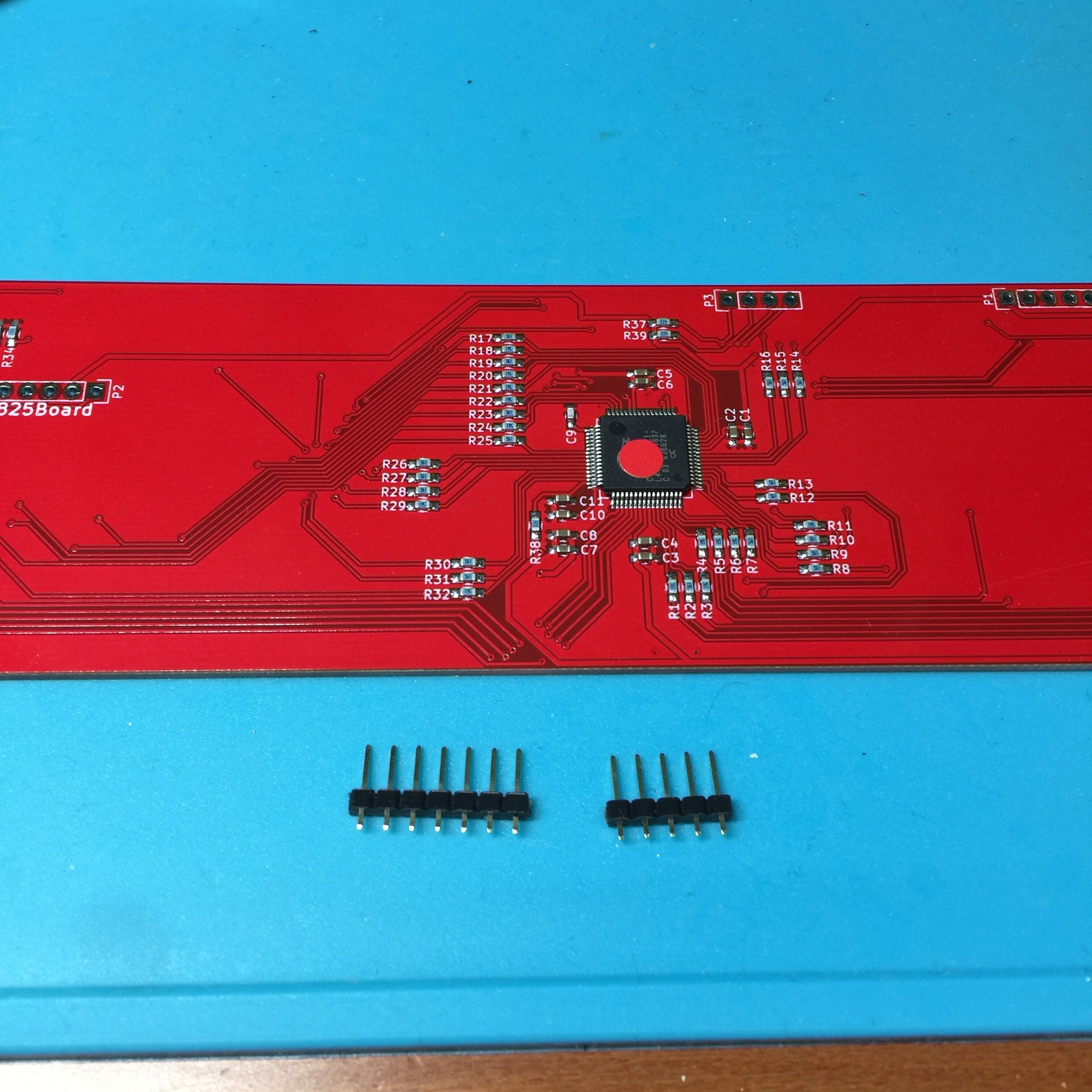
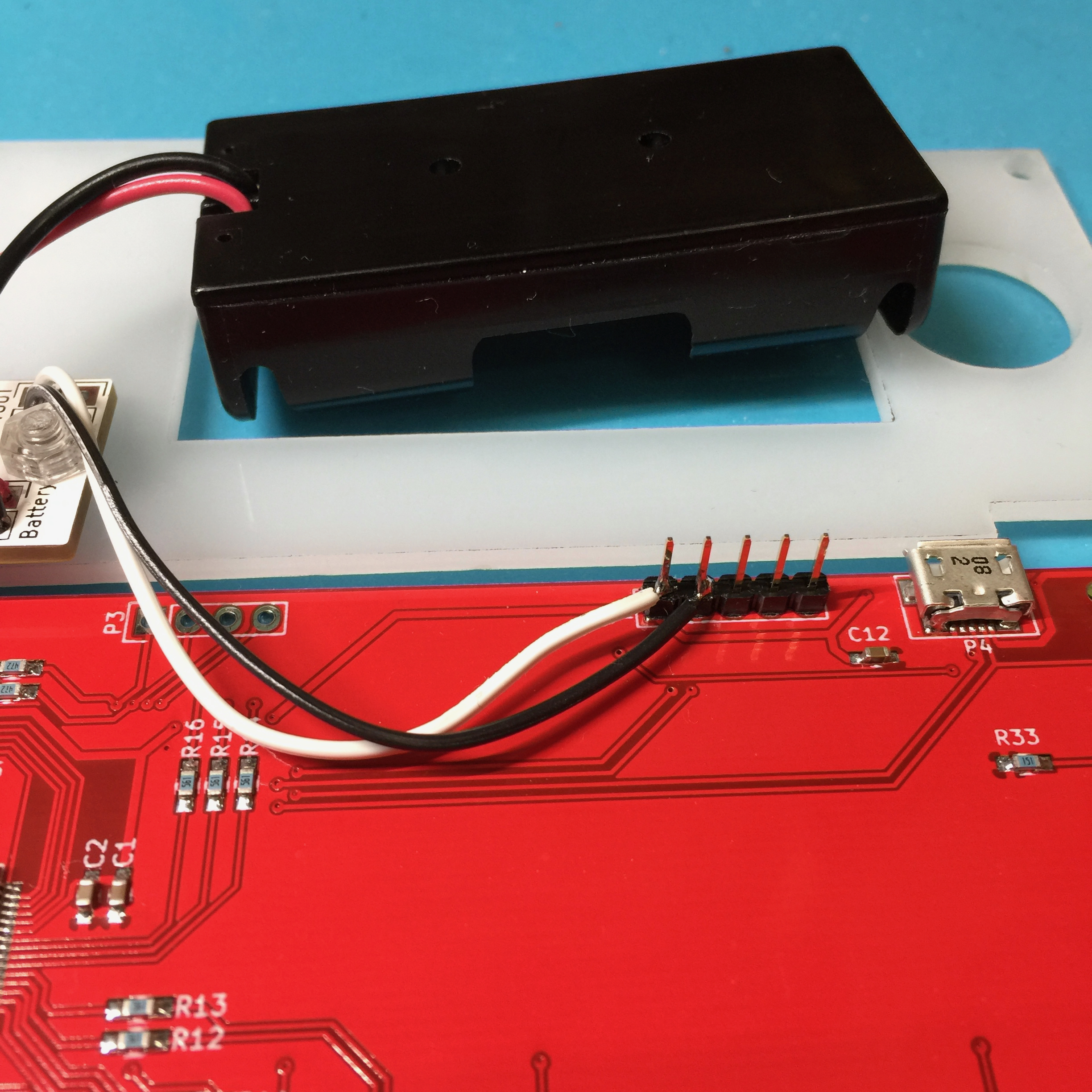
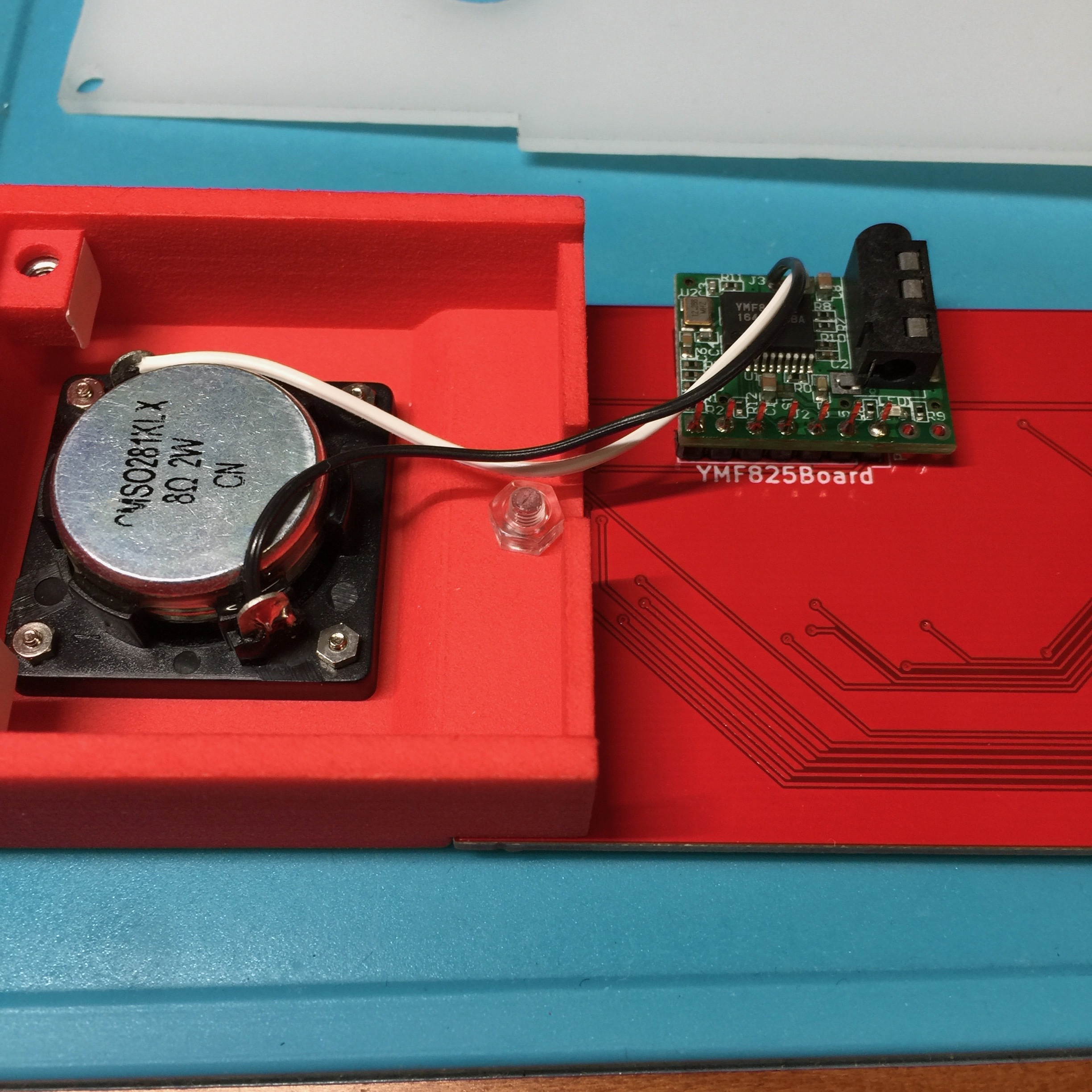
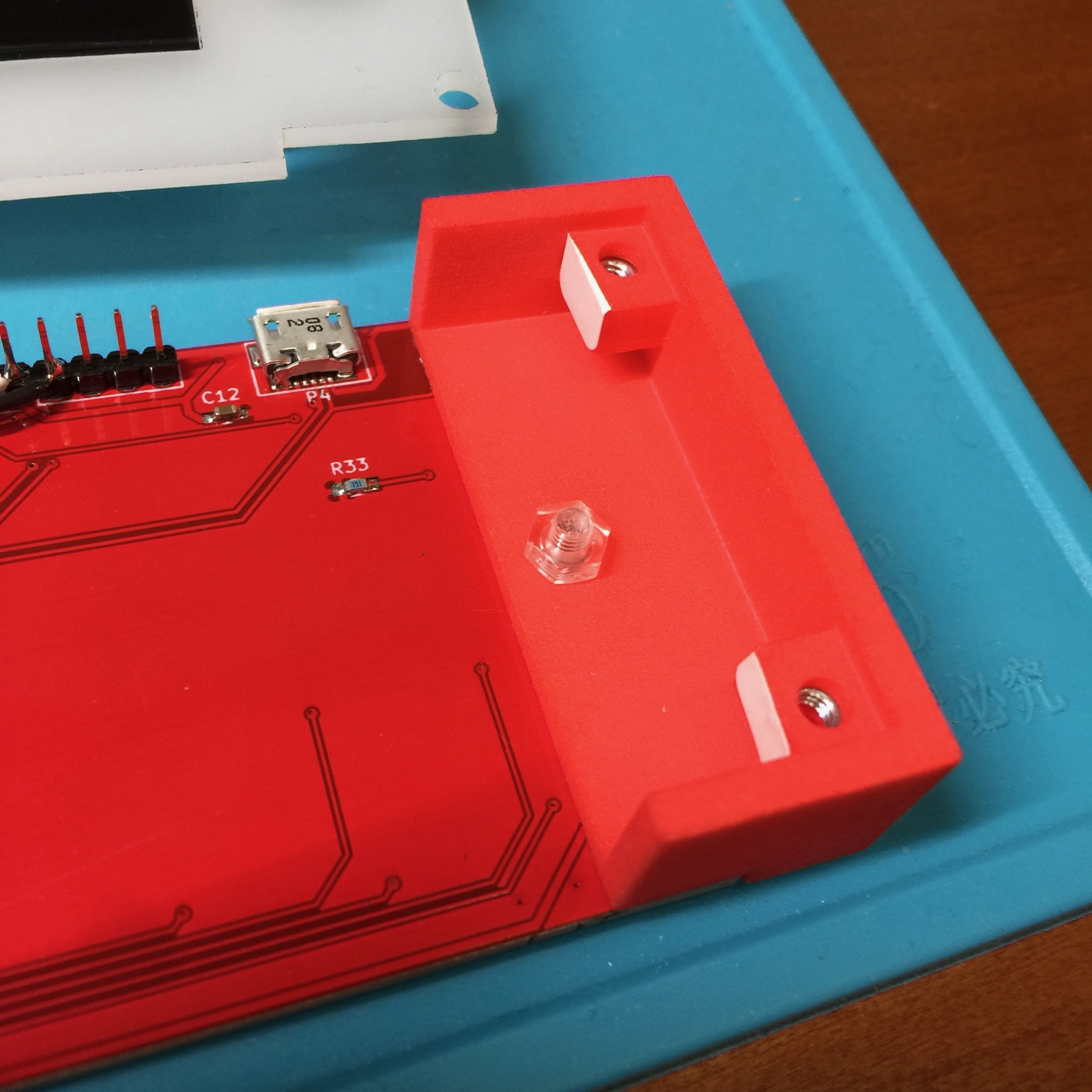
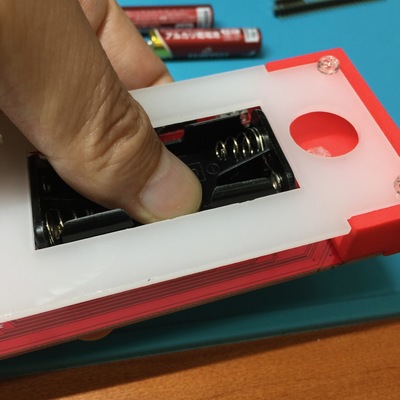
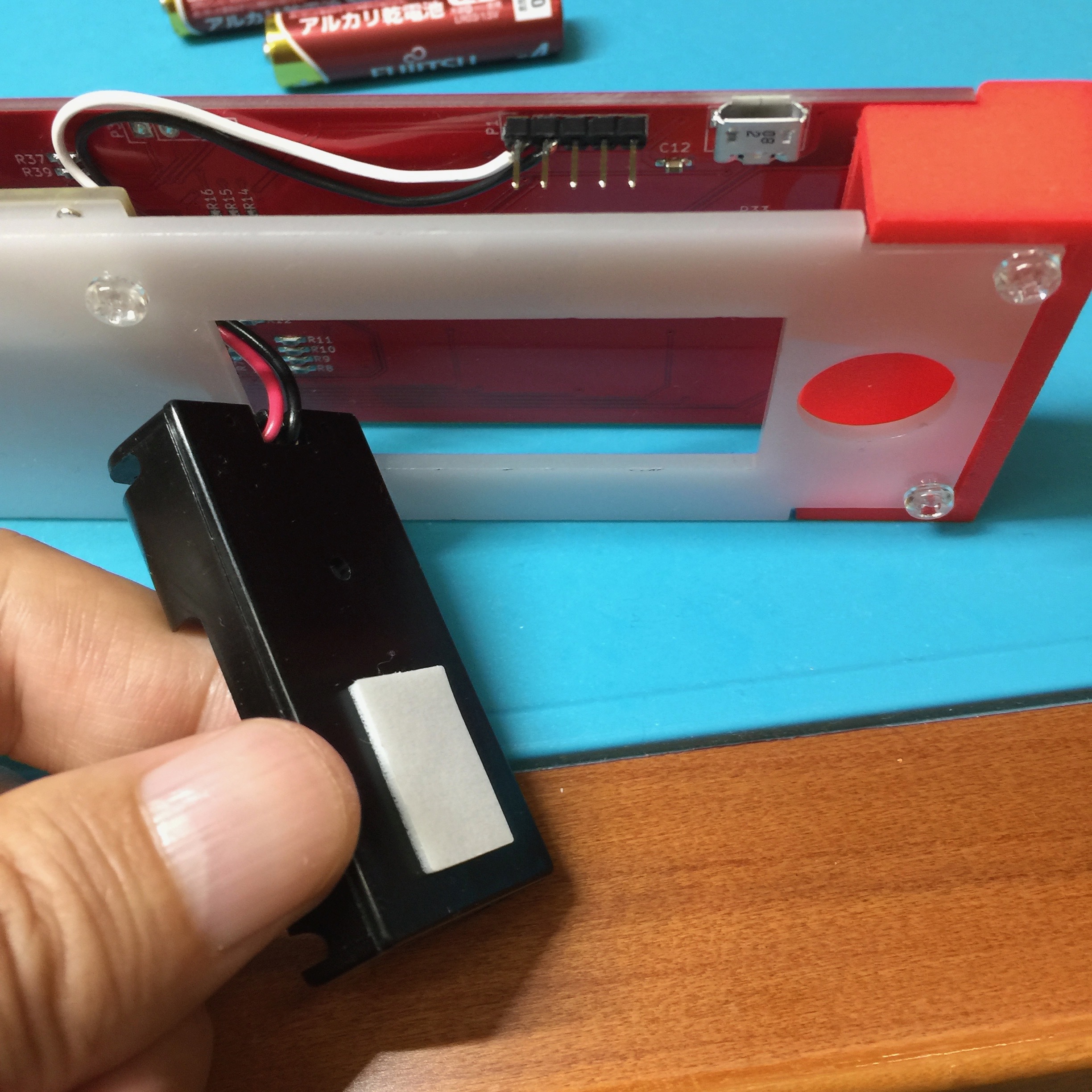
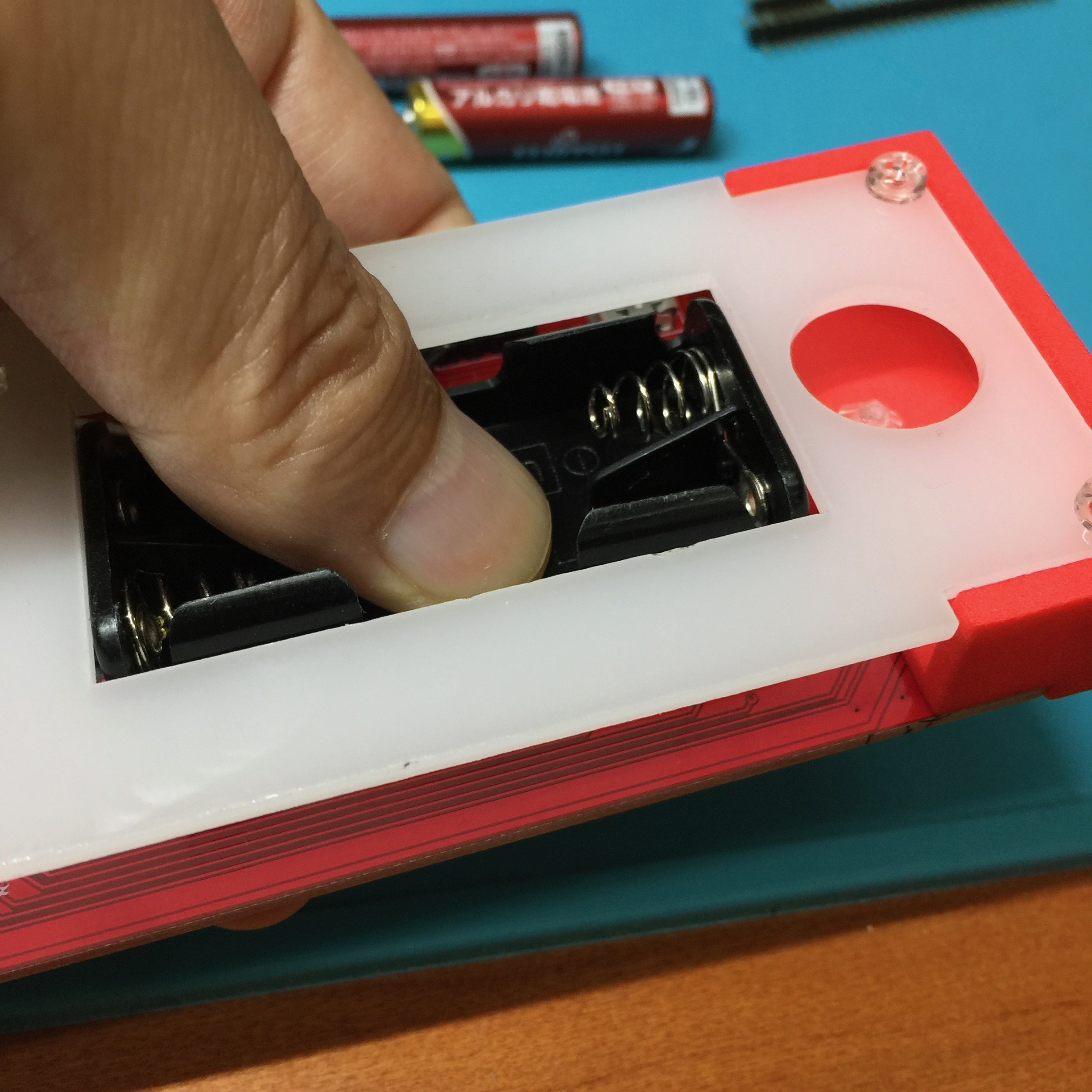
- ・スピーカー(speaker)・3Dプリントによる左右の台座(left/right support by 3D printing)・乳白色のアクリル板による底板(acrylic bottom plate)・昇圧回路モジュール(voltage converter module: VCM)・単4電池ボックス(battery box)・ネジ類(screws)スピーカー取り付け用小型ネジ&ナット:4セット四角ナット:4つ透明ネジ:8つ透明ナット:4つ・ピンヘッダ(pin header)・ケーブル(cable)・両面テープ(double-sided tape)


Comments